Bridge Plug Setting Procedure Step-by-Step Guide for Wireline Operations
How do you properly set a bridge plug using wireline? This step-by-step procedure covers tool string assembly, depth correlation, setting tool activation, and pressure testing for confirmed well isolation. It is written for field engineers who need the exact sequence right the first time, with 200+ Maximus OIGA installations across India, the Middle East, and Southeast Asia behind it
Overview: What the Bridge Plug Setting Procedure Achieves
How do you properly set a bridge plug using wireline? This step-by-step procedure covers tool string assembly, depth correlation, setting tool activation, and pressure testing for confirmed well isolation. It is written for field engineers who need the exact sequence right the first time, with 200+ Maximus OIGA installations across India, the Middle East, and Southeast Asia behind it.
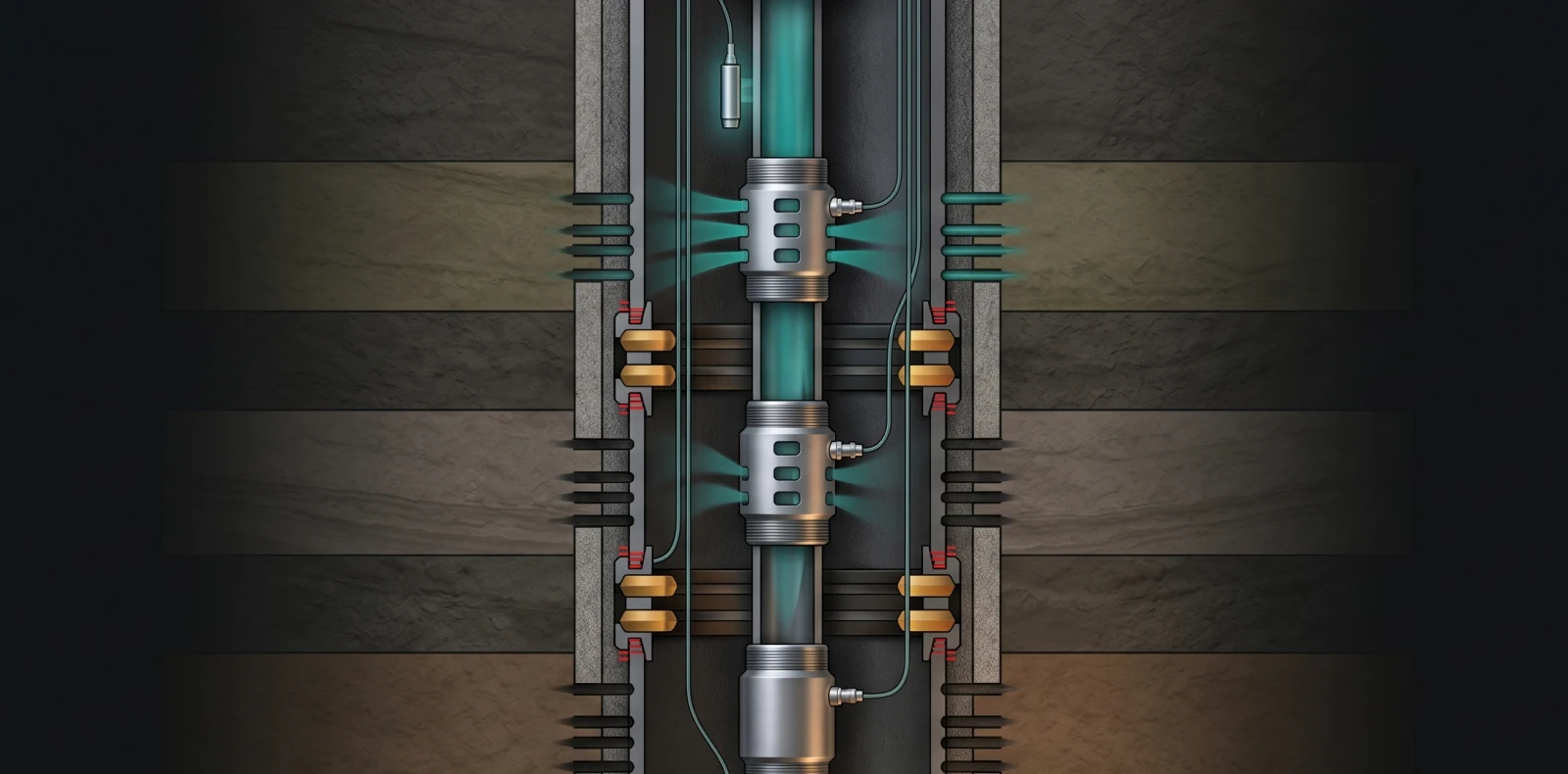
A bridge plug is a downhole tool set to isolate the lower part of a wellbore, available in permanent and retrievable configurations. Wireline setting reduces rig time, risk, and cost compared with tubing-set methods, and the set plug holds pressure from both above and below.
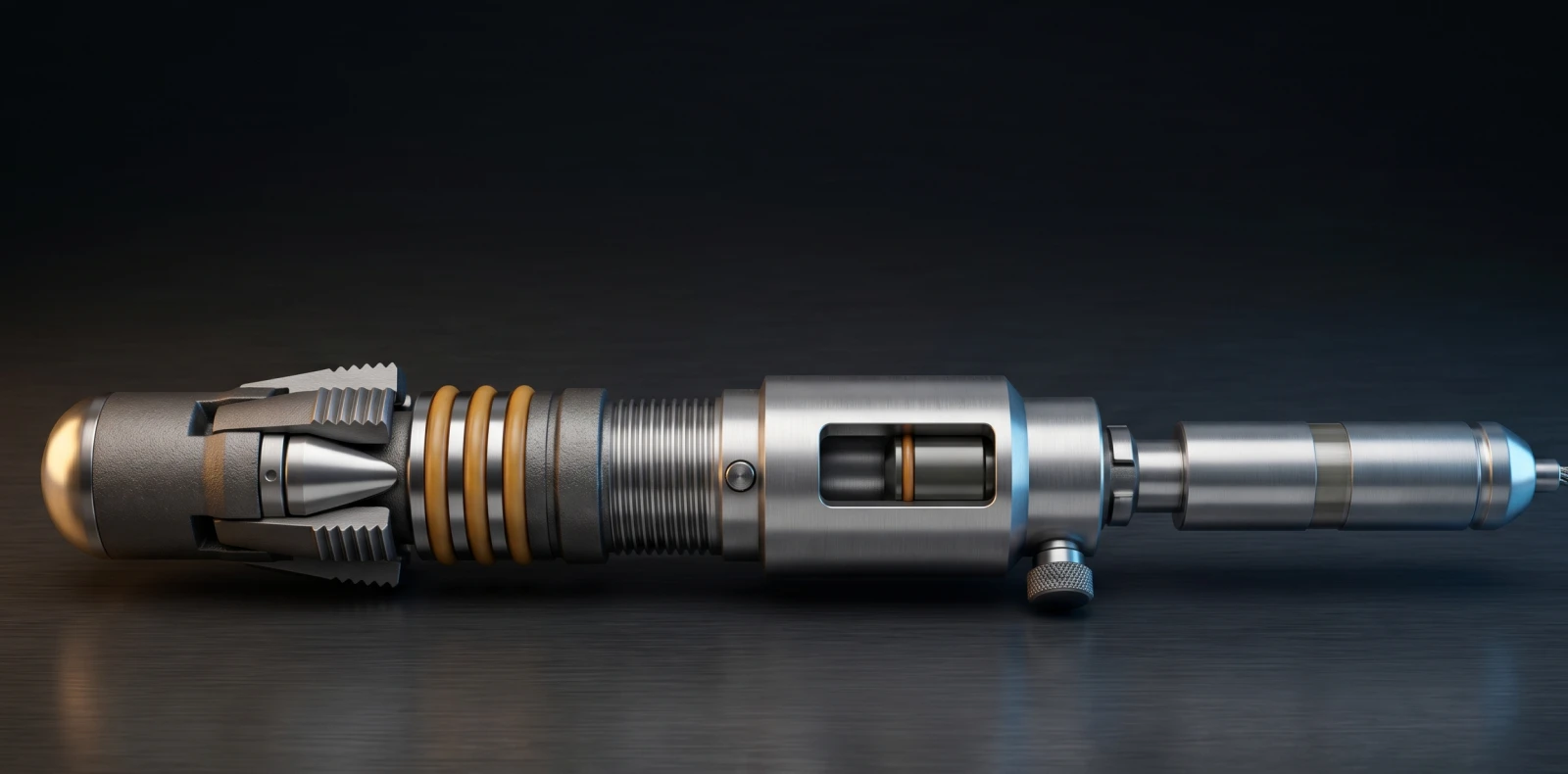
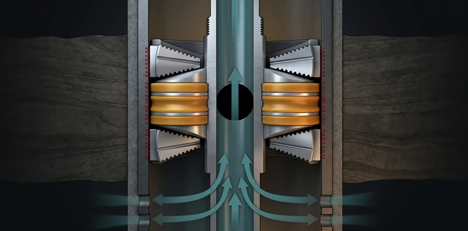
A bridge plug setting procedure isolates a section of cased wellbore using a wireline-deployed mechanical plug. The plug is run on a pressure setting tool, positioned by casing collar locator, then set when the tool's gas charge expands the slips and packing element against the casing — sealing pressure from above and below for testing or abandonment.
What Tools and Equipment Do You Need Before Starting?
The bridge plug must fall within the setting tool's certified temperature and pressure limits before any run begins, and the well must meet defined surface conditions. Pre-job data required includes setting depth, casing size and weight, bottom-hole static temperature at depth, hole deviation, and pressure-test requirements, with the bit/scraper and gauge-ring run already completed.
Casing should have close to 100% cement bond before the plug is run, and the casing bore must be clean — no scale, mud, rust, or cuttings — at the set depth. The correct plug must be selected for the temperature, pressure, casing size, casing weight, and well environment, with the correct crossovers confirmed on location.
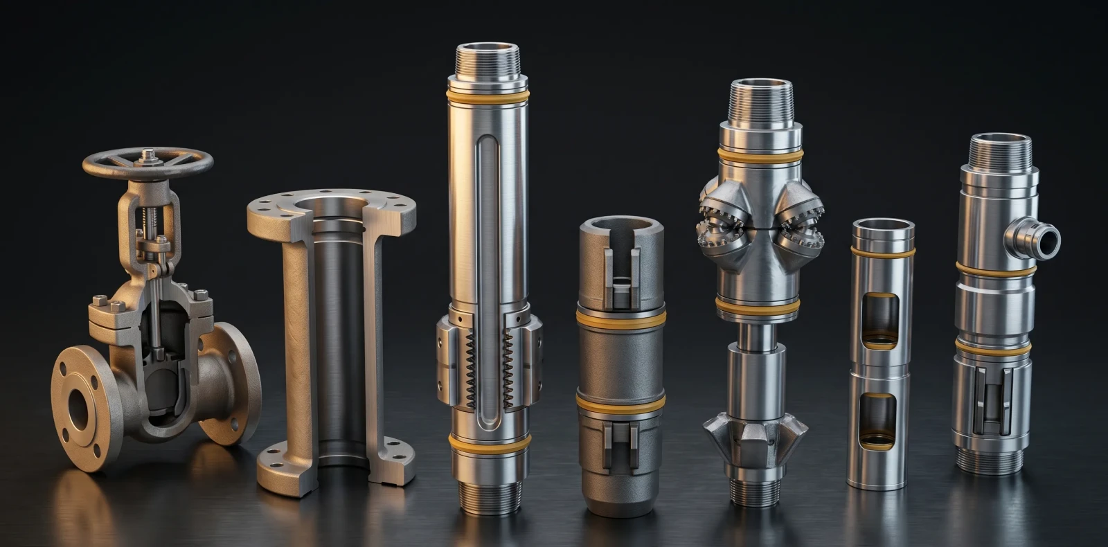
| Equipment / Requirement | Function |
| Bridge plug (cast iron or composite) | Mechanical isolation element — permanent or drill-through |
| Wireline pressure setting tool (WLPSA) | Gas-generating tool that develops hydraulic force to set the plug |
| Casing collar locator (CCL) | Correlates exact setting depth against a known log |
| Lubricator + wireline BOP/rams | Pressure containment and well control during the run |
| Stuffing box / pressure control head | Seals the moving cable; adds containment above the wellhead |
| Clean casing, ~100% cement bond | Bit/scraper and gauge-ring run completed; no scale, mud, or cuttings |
| E-line crew + field engineer | Plug confirmed within certified temperature/pressure limits |
Step 1: Tool String Assembly
Make up the bridge plug to the wireline pressure setting tool, snug-tight only. Install the lock spring or nut according to the setting tool make, and avoid any right-hand rotation at the tool during makeup and run-in.
Verify: the connection is snug, not over-torqued, and the lock device is correctly seated. What can go wrong: over-tightening cracks the slips and can cause premature setting before the plug reaches depth — snug-tight makeup is sufficient.
Step 2: Rig Up and Run-In Hole
Hoist the assembled plug into the lubricator, connect the lubricator to the wellhead, and purge it before running to depth. Guide the tool string through the lubricator, wellhead, and BOP as it is run in.
Verify: the lubricator is purged and pressure-tested before opening to the well. Safety note: the lubricator and wireline rams maintain well control throughout the run-in.
Step 3: Depth Correlation
Use the casing collar locator to correlate the exact setting depth against a known reference log. The final movement to depth must be upward to stretch the wireline and remove slack, fixing the plug at the planned depth before activation.
Accurate setting depth is established with a casing collar locator (CCL), correlating tool position against a known reference log. The final movement to depth must be upward to stretch the wireline and remove slack, ensuring the plug sets at the exact planned depth before the setting tool is activated.
Step 4: Set the Plug
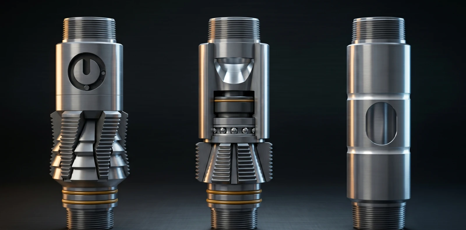
Activate the WLPSA: electrical ignition of the power charge develops hydraulic force gradually. The slips drive into the casing wall, the packing element compresses, and the release stud shears to disconnect the tool.
A wireline pressure setting tool sets the bridge plug by igniting a gas-generating power charge that develops hydraulic force gradually. This force drives the slips into the casing wall and compresses the packing element, then shears a release stud to disconnect the tool — leaving the plug set and the wireline free to recover.
As a certified-limit reference, a Weatherford ISO Ultra Extreme bridge plug has been set at 14,800 ft, 338 deg F (170 deg C), and 15,000 PSI differential to ISO 14310 V0, while the Baker Hughes Model E-4 HP/HT setting tool is rated to 450 deg F (232 deg C) and 25,000 PSI.
Need expert guidance on the right solution?
Talk to our engineers about your project requirements.
Step 5: Release and Recover
Confirm the shear and disconnect, then bleed off tool pressure through the bleeder valve before recovering the wireline and setting tool. Verify: a clean disconnect at surface and stable wellhead pressure.
What can go wrong: failure to bleed off contained pressure before disassembly is a safety hazard — always release pressure through the bleeder valve first.
Step 6: Pressure-Test Verification
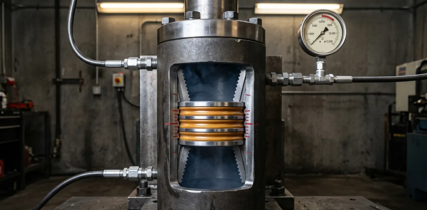
Apply pressure above the set plug and hold it for a defined period. No pressure decline confirms the seal holds its rated differential and zonal isolation is achieved.
Verify: a stable, non-bleeding reading over the hold period. A documented Weatherford HPHT case observed no pressure increase or decrease across the test, confirming a competent barrier before further operations proceeded.
Common Mistakes to Avoid
The most common bridge plug failure is premature (preset) setting, caused by over-tightening the plug onto the setting tool or failed setting-tool O-rings that let wellbore pressure stroke the tool early. Snug-tight makeup is sufficient; over-torque cracks the slips and compromises the seal before the plug reaches depth.
Resting the setting-tool weight on the plug after makeup also cracks the slips, and debris between a slip and the casing can crack slips and trigger a preset. Dirty casing — scale, mud, rust, or cuttings — creates an uneven surface and a leak path under pressure.
Setting force not matched to casing hardness and geometry leaves slips under-engaged and the seal shaky, while over-set damages internals. Right-hand rotation at the setting tool during run-in can back the plug off or prematurely actuate J-systems.
Safety Considerations
The lubricator and wireline rams maintain well control during the run, and those rams are pressure-tested annually by third parties under
well-servicing safety practice. The governing standard, API RP 54, covers occupational safety for well servicing, including wireline service unit placement, lubricators, and wireline operations.
The stuffing box seals the moving cable and the pressure control head adds containment above the wellhead. The WLPSA contains an explosive, gas-generating power charge, so it must be handled per the igniter safety procedure, and tool pressure must be bled off through the bleeder valve before disassembly.
Before the run, confirm the plug is within its certified temperature and pressure limits — a safety-critical check with no performance guarantees implied.
Frequently Asked Questions
How do you set a bridge plug on wireline?
The plug is made up snug-tight to a wireline pressure setting tool, then run into the lubricator and down to depth. A casing collar locator correlates the exact setting depth, with the last movement upward to remove wireline slack. The power charge then fires, developing gradual hydraulic force that sets the slips and packing element, after which the release stud shears and frees the wireline for recovery.
How do you verify a bridge plug is set correctly?
Successful bridge plug setting is confirmed by a pressure test against the set plug: pressure is applied above the plug and held for a defined period with no decline, verifying the seal holds the rated differential. A stable, non-bleeding pressure reading confirms zonal isolation before further operations proceed. For long-term verification, optional pressure/temperature monitoring below the plug can track barrier integrity over time.
What causes a bridge plug to fail or preset?
Over-tightening the plug onto the setting tool cracks the slips and causes premature setting. Failed or missing setting-tool O-rings let wellbore pressure stroke the tool early, producing a preset before the plug reaches depth. Debris between a slip and the casing, or dirty casing at the set depth, prevents a flush seal and creates a leak path under pressure.
What is the difference between a retrievable and a permanent bridge plug?
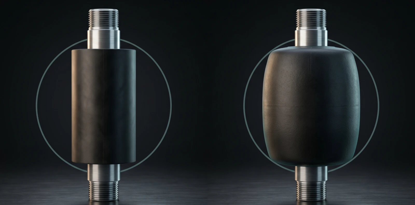
A retrievable bridge plug (RBP) is run and recovered on wireline or tubing for temporary isolation, equalizing pressure before release. A permanent bridge plug — cast iron or composite — is drilled through or milled out and provides a long-term seal for abandonment. Maximus OIGA supplies both material types, cast iron and composite, for either application.
What equipment is needed to set a bridge plug?
The core string is the bridge plug, a wireline pressure setting tool (WLPSA), and a casing collar locator. Well control and pressure containment require a lubricator, wireline BOP/rams, and a stuffing box. Before the run, a bit/scraper and gauge-ring run must be completed and the casing cleaned, with good cement bond confirmed.
Need Engineering Support With This Procedure?
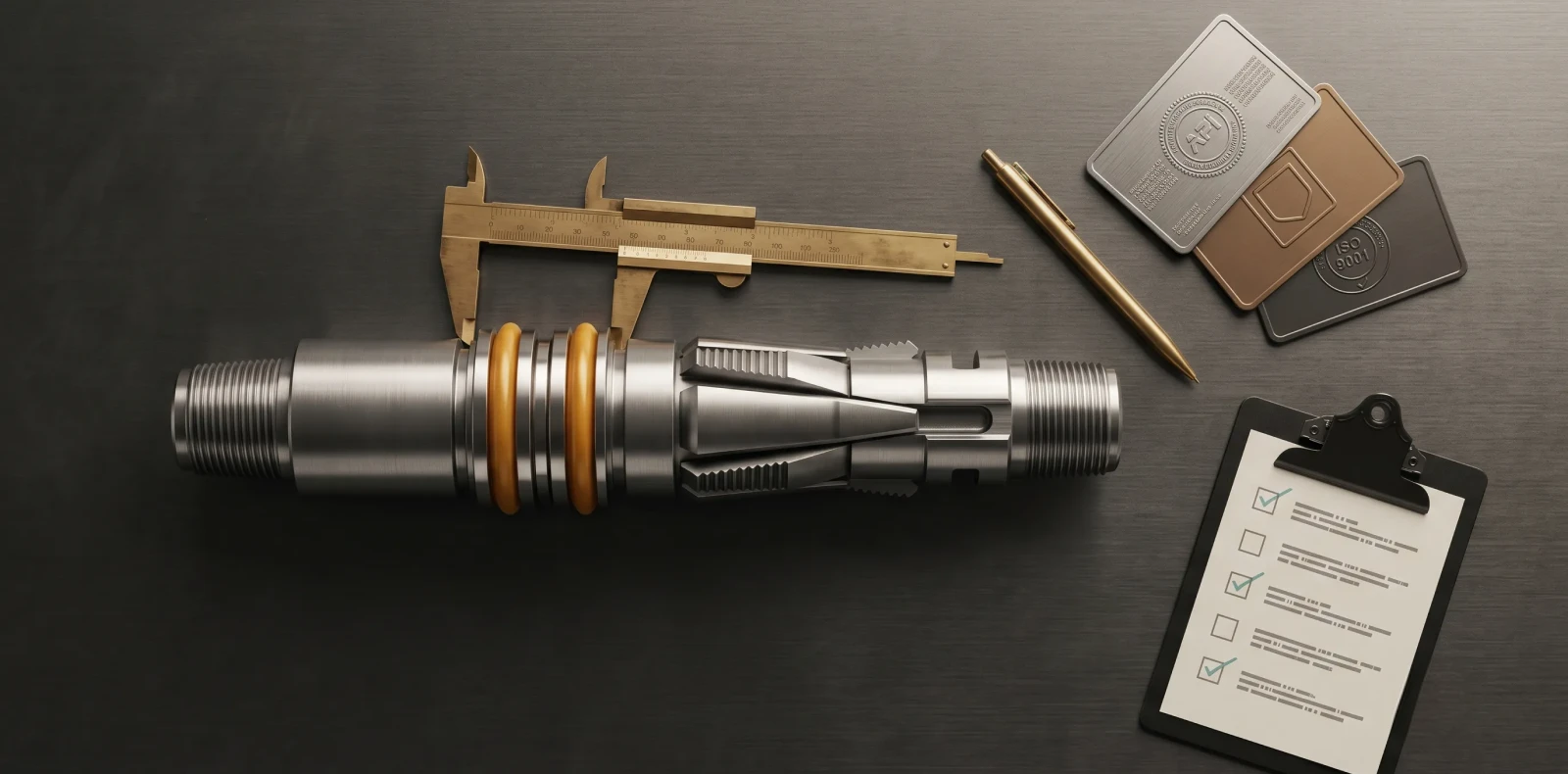
Maximus OIGA manufactures cast iron and composite bridge plugs to API Q1 and ISO 14310, with 200+ installations on record. Need quality bridge plugs for reliable isolation? Request the Maximus OIGA bridge plug product range.
Related Blogs
More Information
Related News & Insights
ISO 14310 & API 11D1 Validation Grades: V6 to V0 Explained
Many engineers assume a higher V-number means a tougher packer. It is the opposite. Under ISO 14310 packer validation grades, the scale runs from V6, the minimum, down to V0, the most demanding gas-tight grade — so a lower number means more severe testing, not less. For anyone just trying to understand the basics, that inversion is where most confusion starts.
June 8, 2026
Intelligent Well Completion: Technologies, Market Trends & Equipment Guide
Imagine adjusting flow from each zone of a multi-zone reservoir in real time, from surface, without ever sending a rig downhole. That is the promise of intelligent well completion, and for an engineer just trying to understand the basics, the concept is more concrete than the marketing suggests once you see how the pieces connect.
June 8, 2026
Oil & Gas Equipment Companies in India: Manufacturer Directory 2026
Navigating India's oilfield equipment landscape is challenging without a comprehensive directory, and procurement teams asking "who are the best manufacturers for this?" often lose weeks to vendor research. This directory profiles the key oil and gas equipment companies in India with verified capabilities, so you can build a qualified shortlist faster.
June 8, 2026
Liner Hanger Types & Selection: Complete Engineering Reference
What type of liner hanger does your well design require? The answer depends on setting depth, liner weight, and whether hydraulic or mechanical actuation suits the hole. For an engineer just trying to understand the basics, the liner hanger types break down into three categories — and knowing how they differ is the first step toward specifying the right one.
June 6, 2026
Packer in Well Completion- Functions, Types & How to Select the Right One
Packers are installed in nearly every cased-hole completion worldwide, yet the packer in well completion remains one of the most consequential pieces of downhole hardware to understand. For anyone just trying to understand the basics, the packer is the component that makes controlled production possible by sealing the space between the tubing and the casing.
June 6, 2026
Swellable Packer Applications- Open Hole, HPHT & Water Shutoff Guide
When an operator needs to isolate an open hole section in a horizontal well without cementing, swellable packer applications offer the most direct route to a reliable annular seal. Across open hole zonal isolation, multistage fracturing, and water shutoff, the swellable packer has become the interventionless tool completion engineers reach for when running cement or mechanical packers is impractical or costly
June 6, 2026
How to Choose an Oilfield Equipment Supplier A Procurement Guide
Choosing the wrong oilfield equipment supplier does not just waste procurement budget; it risks downhole failures that cost ten times the equipment price. Knowing how to choose an oilfield equipment supplier means looking past the catalog and the quotation to the evidence that a vendor can actually deliver safety-critical completion equipment. Procurement engineers who get this right treat the decision as risk management, not purchasing
June 6, 2026
Top Downhole Tool Manufacturers & Suppliers 2026 Global Guide
The global downhole tools market exceeds 5 billion US dollars annually, and the list of companies claiming to serve it is far longer than any procurement team has time to vet. This guide narrows the field: it covers how to evaluate a downhole tool manufacturer, then profiles the global majors, the India-based OEMs, and Maximus OIGA — fairly, with real pros and cons, so you can build an RFQ shortlist without months of vendor research.
June 6, 2026
Sliding Sleeve Applications in Well Completion Types & Selection Guide
Sliding sleeves have evolved from simple open/close mechanisms into precision multi-zone flow control devices, and understanding their applications is now central to modern well completion design. This guide covers what a sliding sleeve does, the main types, real downhole applications, and how to select the right one — written for engineers trying to understand the basics and go a level deeper, not for a sales pitch.
June 6, 2026

HPHT Completion Equipment: Packer & Tool Selection for Extreme Conditions
HPHT wells operating above 300°F and 10,000 PSI require completion equipment rated 2–3× higher than standard applications, with materials and seal designs qualified for the conjunction of pressure and temperature. HPHT completion equipment refers to the packers, bridge plugs, liner hangers, subsurface safety valves, and flow control accessories validated for those conditions. This guide covers how the industry classifies HPHT wells, which equipment categories belong in an HPHT string, how elastomer and metal-seal selection drives performance, and what API and ISO standards engineers cite when verifying ratings.
May 19, 2026