Hydraulic Packer Setting Procedure: Step-by-Step Technical Guide
What is the correct hydraulic packer setting procedure? This step-by-step guide covers tool preparation, pressure calculations, setting sequence, and verification for reliable packer installation in any well configuration.
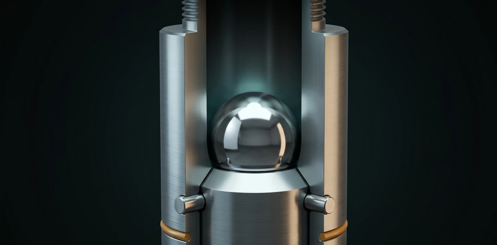
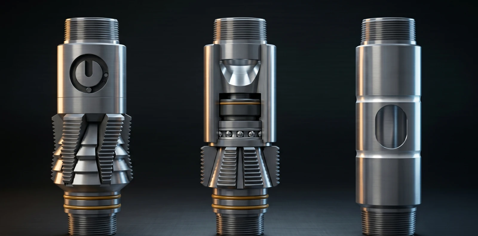
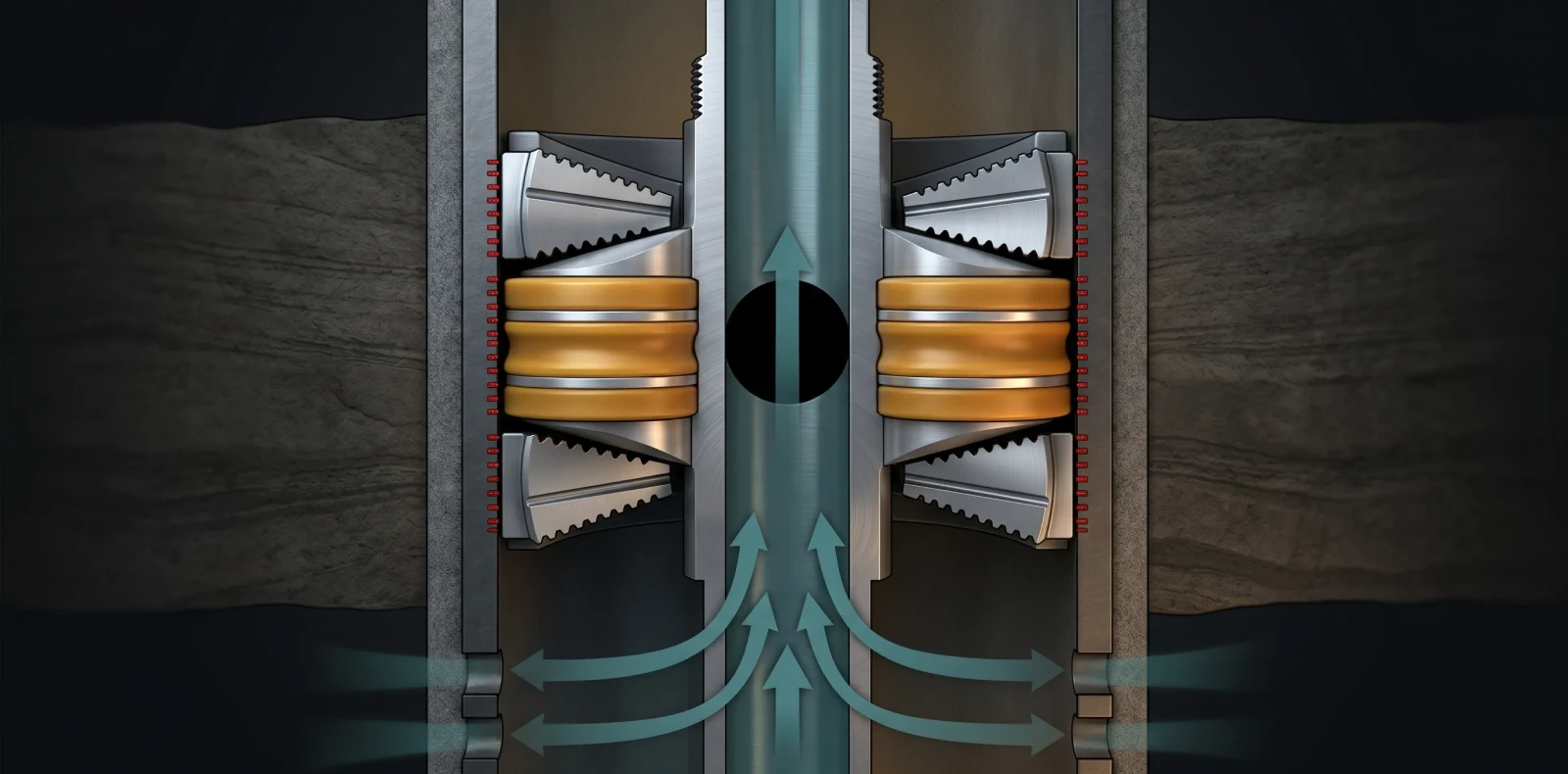
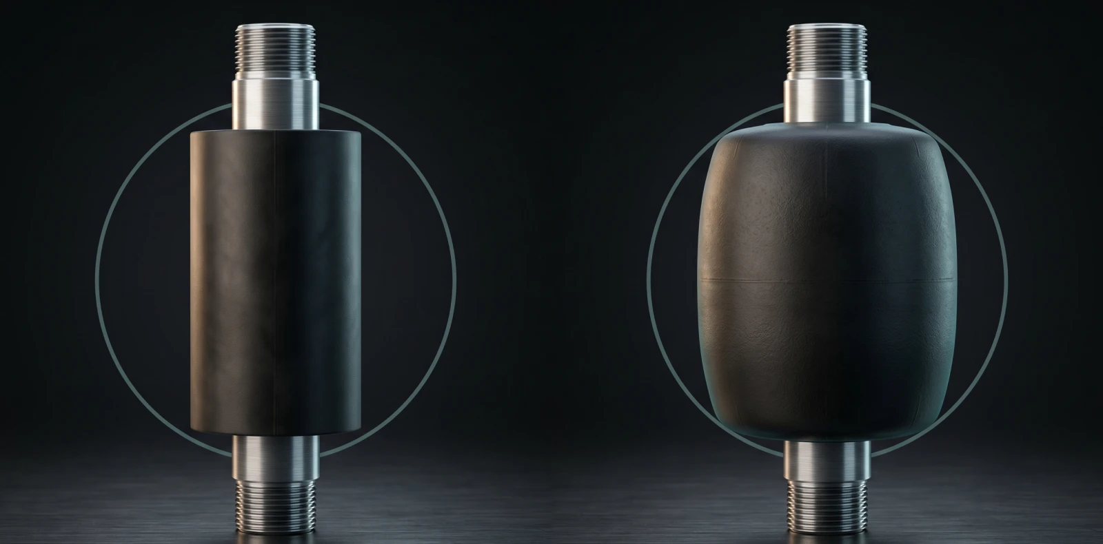
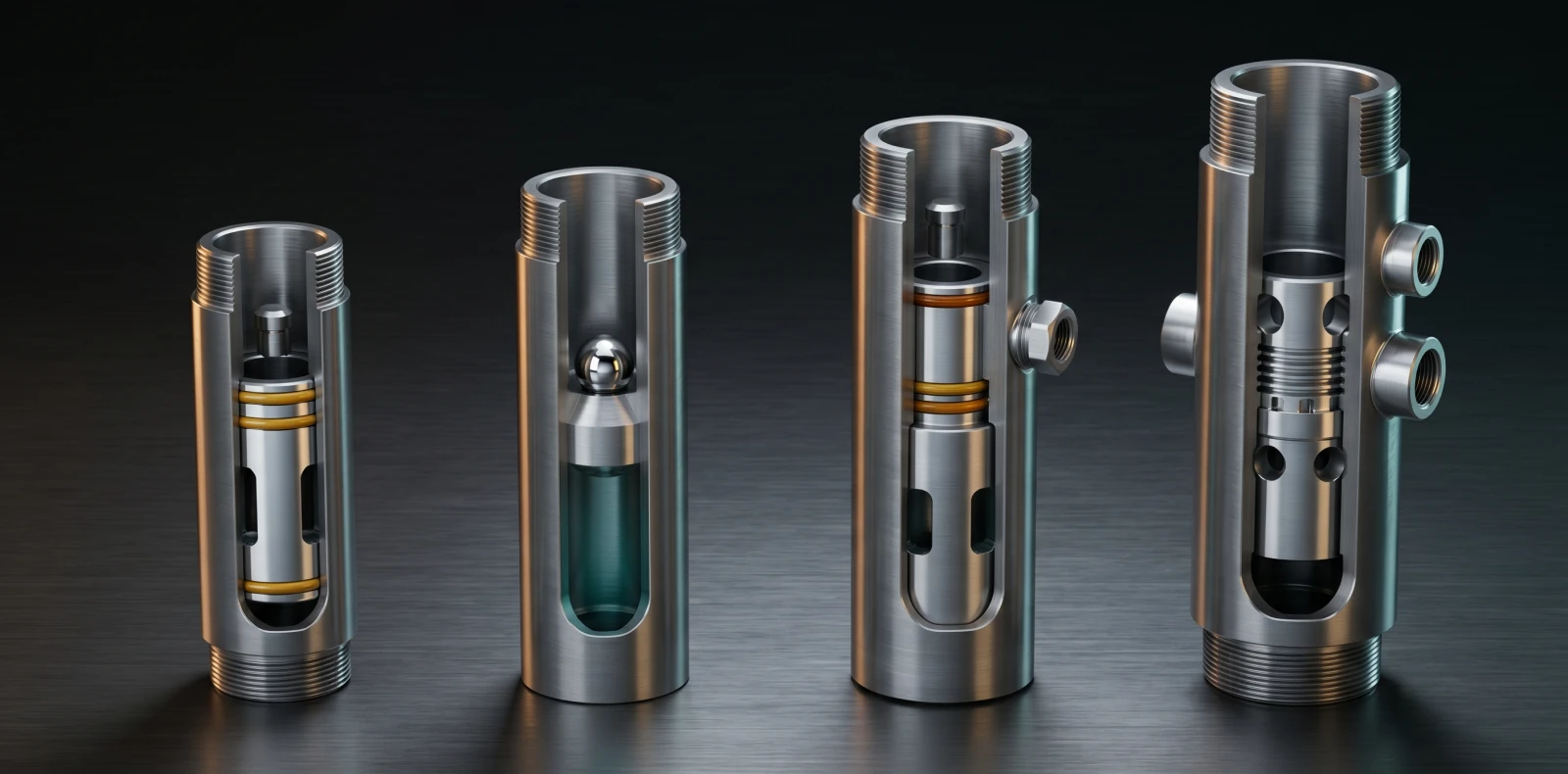
A hydraulic packer is set by applying tubing pressure against a plugging device, typically a dropped ball seated on a sleeve. Pressure shears retaining pins, drives a setting piston downward, energizes the slips against the casing, and compresses the elastomer element to create an annular seal. Pressure is then bled off and the packer remains locked.
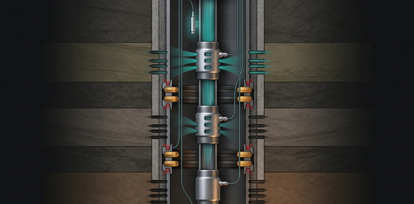
Hydraulic setting is the preferred method for deep wells beyond 12,000 ft (3,658 m) and high-deviation completions where tubing manipulation is impractical.
Equipment You'll Need Before Starting
Hydraulic packer setting requires verified equipment, calibrated pumps, and pre-job pressure testing. Skipping any prerequisite below increases the risk of premature setting, stuck packer, incomplete pack-off, or non-productive time on the workover rig.
| Equipment | Spec / Note |
| Hydraulic setting tool | Compatible with packer model (e.g., Wellcare WC-HST type or equivalent wireline adapter kit) |
| Setting ball | Chrome-steel; size matches ball-seat ID (typically 1.25" primary; 2.125" phenolic G-11 secondary) |
| Cementing / rig pump | Rated to setting pressure plus safety margin; calibrated within 30 days |
| Surface lines | Pressure-tested to 6,000 psi |
| Workstring pop-off valve | Set to 6,000 psi (typical rig standard) |
| Casing pop-off valve | Set to ~3,500 psi (adjust per Pmax calculation) |
| Packer fluid | Clean, filtered; settled solids on top of the packer cause sticking on retrieval |
| Trip-tank | Annulus monitoring during ball gravitation |
| BOP / wellhead | Operational, with rams ready to close on command |
| Crew | Completion engineer, pump operator, BOP/wellhead operator, monitoring engineer |
Tubing must be displaced to a clean packer fluid before run-in. Maximum displacement rate is 3 bbl/min — higher rates can prematurely compress the packer element. Confirm casing condition at the intended setting depth: no collars within 5 ft, per RTTS procedure standard.
Confirm Pmax from weak-link collapse calculations and the packer's differential rating before any pressure is applied. For full equipment specifications and certified spec sheets, reference the hydraulic packer manufacturer page for the PAK VI series.
Step 1: Run-In to Setting Depth
Run-in-hole (RIH) slowly when a plug is set in the bottom nipple. Pressure surges from rapid run-in can prematurely set a hydraulic packer mid-string, requiring fishing or milling to recover.
Avoid drill-string rotation with hydraulic setting tools — some are released by rotation and can be unintentionally activated, leaving the packer at the wrong depth. Understanding how hydraulic packers work begins with respecting these run-in cautions.
At setting depth, work the string across the desired interval. Record weight in/out (WIR-up and WIR-down), and note slack-off and stretch values for later neutral-position reference. Confirm the packer is not within 5 ft of a casing collar — collar geometry interferes with slip bite and seal integrity.
Step 2: Drop Setting Ball & Build Pressure
After running to setting depth, a chrome-steel setting ball is dropped and allowed to gravitate to its seat — typically five minutes per 1,000 ft. Once seated, tubing pressure is built incrementally in 500 psi steps with two-minute hold periods, monitoring for any pressure decay that would indicate debris on the ball seat.
Drop the chrome-steel setting ball at surface — 1.25" diameter for the HRWP example; verify size against ball-seat ID for the specific model. Place the annulus on trip-tank during ball fall to monitor for losses.
Once seated, perform a stepped low-pressure verification before the main setting cycle. The shear pin holds body and mandrel together until setting pressure begins to act, so this verification confirms a clean ball seat without committing to setting pressure.
If pressure does not hold for two minutes at 500 psi, reverse-circulate to clear ball-seat debris — never above 250 psi or 10 bbls. In low bottom-hole pressure or vacuum wells, start the low-pressure test at 100–200 psi to detect early shear.
Step 3: Apply Setting Pressure (Stepped Schedule)
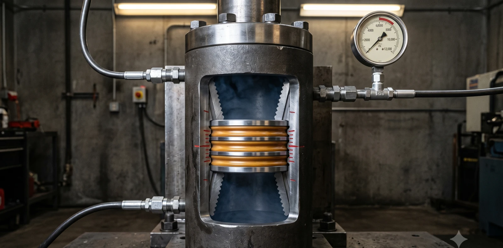
Industry practice for hydraulic packer setting follows a stepped pressure schedule: 500 psi, 1,000 psi, 1,500 psi, 2,000 psi each held for two minutes, followed by a final pressure of approximately 2,500–2,600 psi held for ten minutes. Successful holds at every step confirm the packer slips have engaged and the seal element has packed off.
| Step # | Pressure (psi) | Hold Time (min) | Verification Check |
| 1 | 500 | 2 | Confirm hold; if decay → reverse-circulate ≤250 psi |
| 2 | 1,000 | 2 | Confirm hold; pressure decay indicates ball-seat debris |
| 3 | 1,500 | 2 | Confirm hold; initial slip-set pressure for many tools |
| 4 | 2,000 | 5 | Extended hold; confirms clean shear-pin behavior |
| 5 (final) | 2,500–2,600 | 10 | Energizes slips and packs off element; lock ring engages |
The Wellcare WC-HP-1 reference confirms 2,500 psi as the standard set pressure for production-class hydraulic-set retrievables. The Wellcare WC-HST setting tool initially applies ~1,500 psi to set slips, then increments in 100–200 psi steps to fully set and shear the release stud.
Pressure increase must be gradual — 500 psi increments with hold periods between each step. Sudden spikes shear the release stud before slip engagement is confirmed. If 2,600 psi cannot be achieved due to premature ball-seat shear (~2,100 psi shear floor), drop the secondary 2.125" phenolic G-11 ball and repeat the schedule.
Setting force is locked into the packer by the body lock ring. Once set, the pressure increment / pack-off step is irreversible — slack-off transfers into the packing element; up-strain transfers through the shear ring to the slip ring.
Step 4: Verify Slip Engagement & Pack-Off
Bleed off tubing pressure to zero before any mechanical verification. Pressure must be at zero so the anchor test reads only the mechanical contribution of the slips, not residual hydraulic preload.
Anchor test: apply 10-kip overpull, then 10-kip set-down on the packer. Both directions must hold — overpull confirms upper slip bite; set-down confirms lower slip engagement. If either fails, the packer has not set and must be released and re-run.
If the anchor test passes, set down the workstring with 4 kips and close the BOP. After the packer is set, a further pressure increase shears the ball-seat pin so the ball and seat fall out of the bottom of the tubing — restoring full tubing ID for production.
Step 5: Pressure-Test the Packer Seal
Apply 500 psi to the annulus for 10 minutes via the rig pump. Monitor backside pressures and workstring returns continuously throughout the hold — any decay or returns indicate an incomplete seal that must be diagnosed before continuing.
If 500 psi holds for the full 10 minutes, continue pressure-up to 3,000 psi for 5 minutes to release the service tool from the packer. Slowly release annular pressure to zero — never bleed pressure suddenly. Mark the workstring at the rig floor to indicate the neutral landing position.
API Specification 11D1 and ISO 14310 define the pressure-test design verification context. V-grade testing requires two pressure reversals with minimum 15-minute hold periods in each direction. V0 and V1 grades use gas (air or nitrogen) as the test medium and allow 20 cm³ leakage; V2–V5 grades use water or hydraulic oil.
Common Mistakes to Avoid
These common mistakes account for the majority of premature setting events, stuck packers, and failed pressure tests.
- Running in too fast with a plug installed. Pressure surges prematurely set the packer mid-string.
- Skipping the low-pressure stepped verification. Masks ball-seat debris and causes a stuck setting cycle.
- Exceeding the maximum tubing displacement rate. Above 3 bbl/min, the elastomer element compresses prematurely.
- Pressuring up too aggressively. Sudden spikes shear the release stud before slips are confirmed engaged.
- Setting within 5 ft of a casing collar. Slip bite and seal integrity are compromised.
- Not monitoring the trip-tank during ball gravitation. Undetected annulus losses indicate well-control issues.
- Setting in oxygen-rich packer fluid. Long-term corrosion seizes slips, requiring milling on workover.
- Failing to record neutral position before bleed-off. The operator cannot confirm tubing landing for production.
For stuck packer recovery, estimate stuck depth using the stretch formula (overpull required to induce 3.5" stretch per 1,000 ft of free pipe). See stuck-pipe procedures for full diagnostics; milling is required if slips are corroded shut.
Safety Considerations
Confirm Pmax from weak-link collapse calculations and the packer's differential rating before setting pressure is applied. Pop-off valves are set to 6,000 psi on the workstring and ~3,500 psi on the casing, adjusted per Pmax. API 11D1 compliance requires using packers tested to a documented V-grade matching well conditions — V0/V1 for gas service, V3 for liquid service with thermal cycling.
Maintain BOP rams closed during pressure-up and monitor the backside continuously. Crew briefing must cover the setting pressure target, hold-decay tolerance, abort criteria, and the emergency-bleed procedure. Never exceed 250 psi during reverse circulation.
Frequently Asked Questions
How do you set a hydraulic packer?
Run to setting depth, drop the chrome-steel ball (~5 minutes per 1,000 ft to gravitate), then build pressure incrementally — 500, 1,000, 1,500, 2,000 psi for 2 minutes each — followed by 2,500–2,600 psi for 10 minutes to energize the slips and pack off. Verify with a 10-kip overpull / set-down anchor test, then pressure-test the annulus to 500 psi for 10 minutes.
How do you verify a hydraulic packer is set correctly?
Setting verification has two gates: a mechanical anchor test using 10-kip overpull followed by 10-kip set-down to confirm slip engagement, and a hydraulic seal test by pressuring the annulus to 500 psi for ten minutes. Both must hold without bleed-off before the service tool is released from the packer.
Tool release follows at 3,000 psi for 5 minutes. Any decay during either test indicates an incomplete set.
What pressure is needed to set a hydraulic packer?
Industry-standard final setting pressure is 2,500 psi (Wellcare) up to 2,600 psi (HRWP). Tools like the Wellcare WC-HST type apply ~1,500 psi for initial slip-set, then increment in 100–200 psi steps to fully set and shear the release stud. Always confirm against the manufacturer's spec sheet — values vary by piston area and seal element. Pmax must not be exceeded.
What happens if a hydraulic packer doesn't set?
The most common cause is debris on the ball seat preventing pressure-hold at the 500 psi verification step. Bleed off and reverse-circulate to clear — never above 250 psi or 10 bbls. Repeat the stepped schedule from 500 psi upward. If the seat shears prematurely (~2,100 psi shear floor), drop the secondary 2.125" phenolic G-11 ball. If pressure never builds, suspect a tubing leak, plug failure, or wrong ball size — pull and inspect.
Engineering Support & Equipment
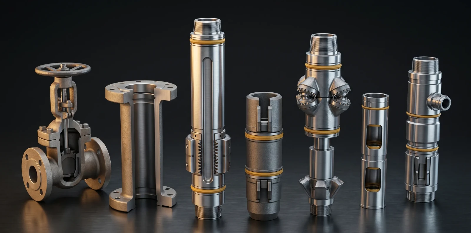
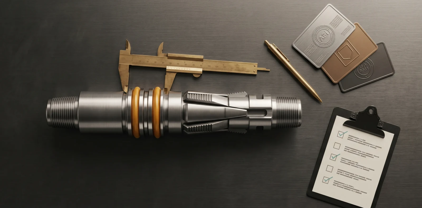
Need reliable hydraulic packers? Maximus OIGA's PAK VI series is API Q1 and ISO 14310 certified, with 200+ documented installations across India, the Middle East, and Southeast Asia. Request specifications and engineering will respond within one business day.
Related
- ISO 14310 & API 11D1 Validation Grades: V6 to V0 Explained
- Intelligent Well Completion: Technologies, Market Trends & Equipment Guide
- Oil & Gas Equipment Companies in India: Manufacturer Directory 2026
- Liner Hanger Types & Selection: Complete Engineering Reference
- Packer in Well Completion- Functions, Types & How to Select the Right One
- Swellable Packer Applications- Open Hole, HPHT & Water Shutoff Guide
- How to Choose an Oilfield Equipment Supplier A Procurement Guide
- Top Downhole Tool Manufacturers & Suppliers 2026 Global Guide
- Sliding Sleeve Applications in Well Completion Types & Selection Guide
- Bridge Plug Setting Procedure Step-by-Step Guide for Wireline Operations
More Information
Related News & Insights
ISO 14310 & API 11D1 Validation Grades: V6 to V0 Explained
Many engineers assume a higher V-number means a tougher packer. It is the opposite. Under ISO 14310 packer validation grades, the scale runs from V6, the minimum, down to V0, the most demanding gas-tight grade — so a lower number means more severe testing, not less. For anyone just trying to understand the basics, that inversion is where most confusion starts.
June 8, 2026
Intelligent Well Completion: Technologies, Market Trends & Equipment Guide
Imagine adjusting flow from each zone of a multi-zone reservoir in real time, from surface, without ever sending a rig downhole. That is the promise of intelligent well completion, and for an engineer just trying to understand the basics, the concept is more concrete than the marketing suggests once you see how the pieces connect.
June 8, 2026
Oil & Gas Equipment Companies in India: Manufacturer Directory 2026
Navigating India's oilfield equipment landscape is challenging without a comprehensive directory, and procurement teams asking "who are the best manufacturers for this?" often lose weeks to vendor research. This directory profiles the key oil and gas equipment companies in India with verified capabilities, so you can build a qualified shortlist faster.
June 8, 2026
Liner Hanger Types & Selection: Complete Engineering Reference
What type of liner hanger does your well design require? The answer depends on setting depth, liner weight, and whether hydraulic or mechanical actuation suits the hole. For an engineer just trying to understand the basics, the liner hanger types break down into three categories — and knowing how they differ is the first step toward specifying the right one.
June 6, 2026
Packer in Well Completion- Functions, Types & How to Select the Right One
Packers are installed in nearly every cased-hole completion worldwide, yet the packer in well completion remains one of the most consequential pieces of downhole hardware to understand. For anyone just trying to understand the basics, the packer is the component that makes controlled production possible by sealing the space between the tubing and the casing.
June 6, 2026
Swellable Packer Applications- Open Hole, HPHT & Water Shutoff Guide
When an operator needs to isolate an open hole section in a horizontal well without cementing, swellable packer applications offer the most direct route to a reliable annular seal. Across open hole zonal isolation, multistage fracturing, and water shutoff, the swellable packer has become the interventionless tool completion engineers reach for when running cement or mechanical packers is impractical or costly
June 6, 2026
How to Choose an Oilfield Equipment Supplier A Procurement Guide
Choosing the wrong oilfield equipment supplier does not just waste procurement budget; it risks downhole failures that cost ten times the equipment price. Knowing how to choose an oilfield equipment supplier means looking past the catalog and the quotation to the evidence that a vendor can actually deliver safety-critical completion equipment. Procurement engineers who get this right treat the decision as risk management, not purchasing
June 6, 2026
Top Downhole Tool Manufacturers & Suppliers 2026 Global Guide
The global downhole tools market exceeds 5 billion US dollars annually, and the list of companies claiming to serve it is far longer than any procurement team has time to vet. This guide narrows the field: it covers how to evaluate a downhole tool manufacturer, then profiles the global majors, the India-based OEMs, and Maximus OIGA — fairly, with real pros and cons, so you can build an RFQ shortlist without months of vendor research.
June 6, 2026
Sliding Sleeve Applications in Well Completion Types & Selection Guide
Sliding sleeves have evolved from simple open/close mechanisms into precision multi-zone flow control devices, and understanding their applications is now central to modern well completion design. This guide covers what a sliding sleeve does, the main types, real downhole applications, and how to select the right one — written for engineers trying to understand the basics and go a level deeper, not for a sales pitch.
June 6, 2026
Bridge Plug Setting Procedure Step-by-Step Guide for Wireline Operations
How do you properly set a bridge plug using wireline? This step-by-step procedure covers tool string assembly, depth correlation, setting tool activation, and pressure testing for confirmed well isolation. It is written for field engineers who need the exact sequence right the first time, with 200+ Maximus OIGA installations across India, the Middle East, and Southeast Asia behind it
June 6, 2026