Landing Nipple in Oil & Gas: Types, Specifications & Selection
What is a landing nipple, and why is it critical for downhole flow control? This guide covers how landing nipples work, how selective and no-go variants differ, the F, R, X, XN, RN, and RPT profiles in common use, and the material grades that govern selection for sweet, sour, and HPHT service.
What is a landing nipple, and why is it critical for downhole flow control?
This guide covers how landing nipples work, how selective and no-go variants differ, the F, R, X, XN, RN, and RPT profiles in common use, and the material grades that govern selection for sweet, sour, and HPHT service.
Why Landing Nipples Matter in Flow Control
If you are just trying to understand the basics before specifying flow control hardware, start here: without landing nipples, there is no defined seat for setting plugs or safety valves. Every flow control intervention depends on a precise mechanical lock and a pressure-tight seal — and the landing nipple is what makes both possible.
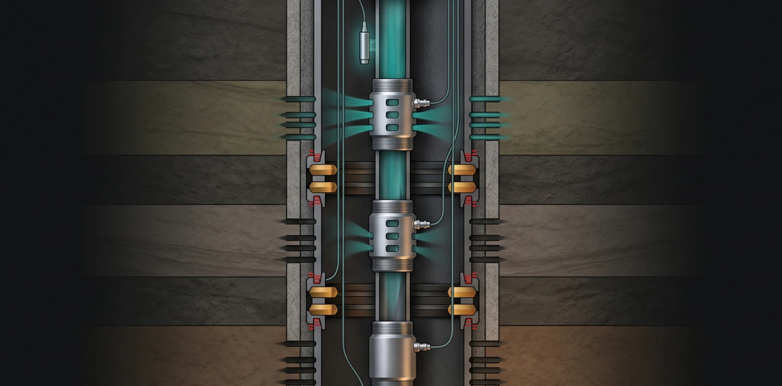
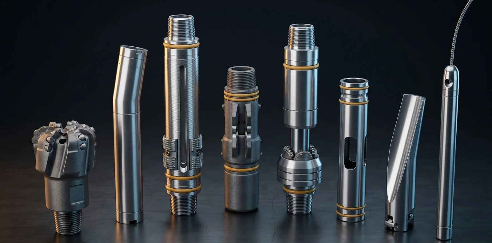
Landing nipples support three primary applications: isolation and plugging operations, installation of downhole flow regulators (subsurface safety valves, chokes), and the landing of pressure and temperature gauges. They are present in most tubing-deployed completions, which is why every serious flow control manufacturer treats landing nipple design as a core engineering discipline rather than a commodity item.
The economic stakes are direct: a wrong-size or defective nipple means the wireline crew cannot set a plug or safety valve — a lost production day or a workover trip.
What Is a Landing Nipple? Anatomy & Function
The canonical definition appears in the Schlumberger Energy Glossary. The engineering anatomy is straightforward.
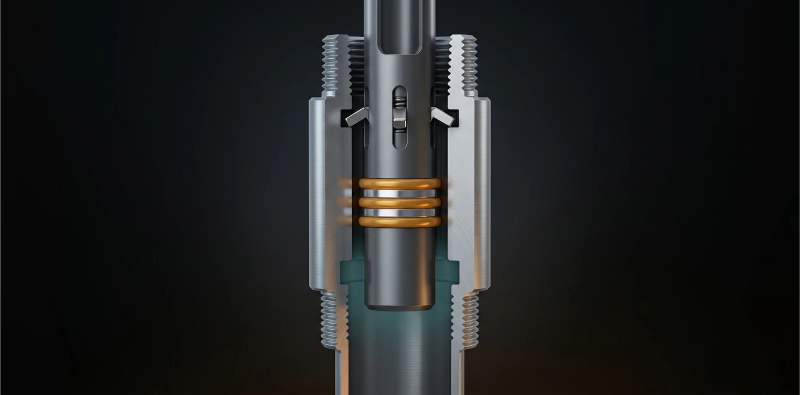
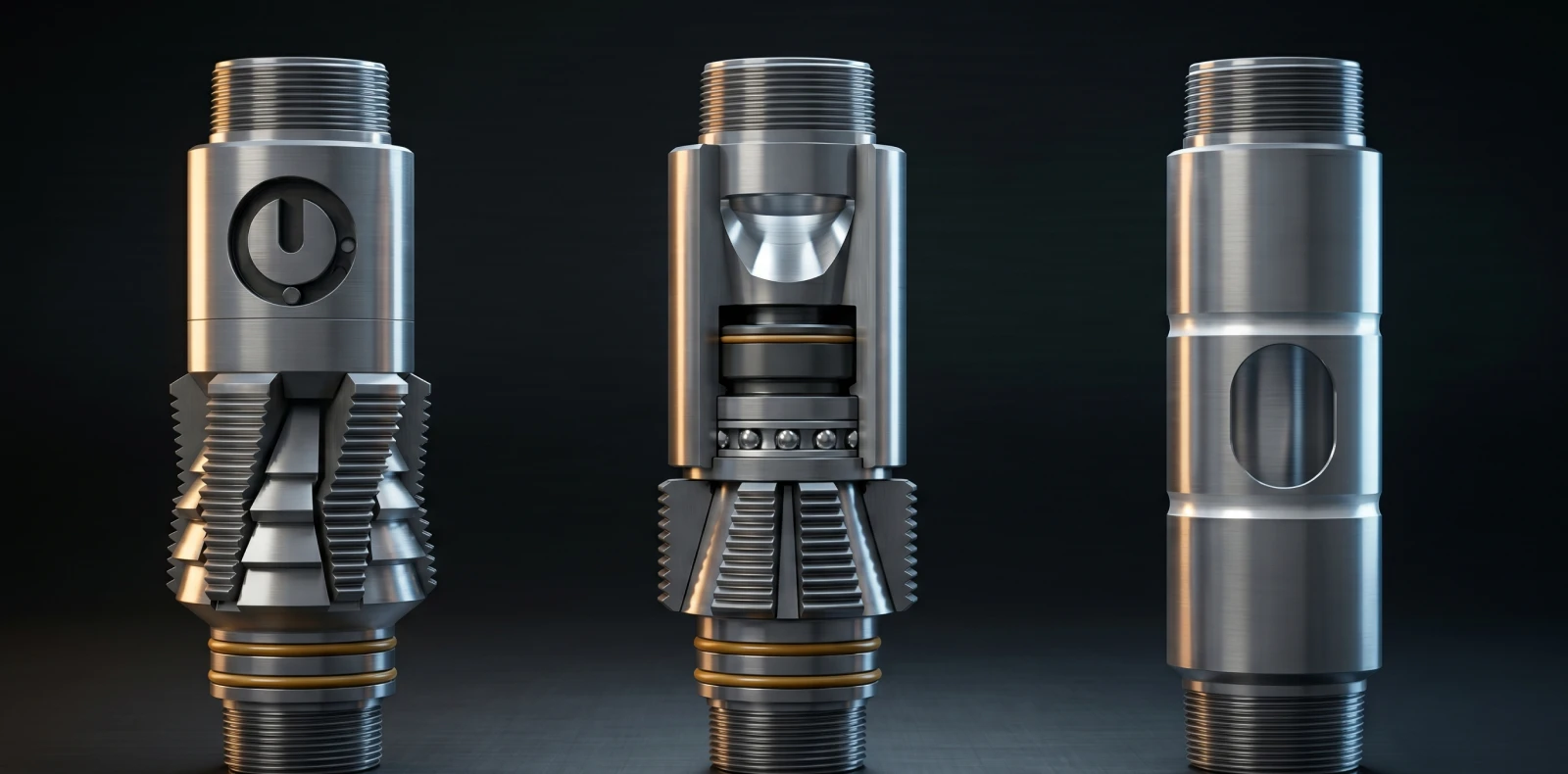
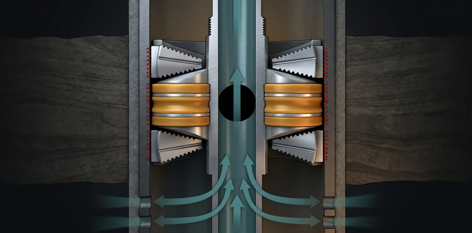
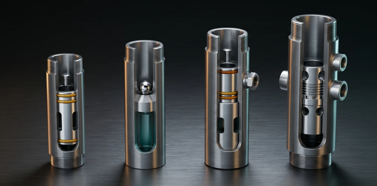
The wall is thicker than standard tubing because the locking shoulder concentrates stress at one point. When a lock mandrel is run on slickline, jarring drives the locking dogs into the recess and the mandrel's packing seals against the polished bore — a pressure-tight, mechanically locked connection holding pressure from above or below.
Connection types follow the production string: API EUE 8-round threads are standard, with NU and premium thread families (VAM, Tenaris, JFE) specified where the string demands them.
Types of Landing Nipples: Selective vs No-Go
Selective landing nipples use one of three selectivity methods: variable internal profile, running-tool actuation (the dominant approach, used in Halliburton's X and R series), or pre-spaced magnets. The advantage is placement flexibility — landing depth is chosen on each wireline trip.
No-go landing nipples take the opposite approach: a reduced internal diameter physically blocks the mandrel, giving positive seating indication and a barrier against dropped tools — which is why the no-go is typically placed deepest.
A third hybrid — the ported or safety-valve nipple — communicates hydraulic control line pressure to a wireline-retrievable subsurface safety valve, covered by the API standard for safety-valve equipment.
| Feature | Selective Landing Nipple | No-Go Landing Nipple |
| ID profile | Same internal diameter — running tool determines lock position | Reduced internal diameter — physically stops the mandrel |
| Quantity per string | Multiple same-size nipples can coexist | Typically one (positioned deepest) |
| Position in string | At any planned interval | Bottom of the nipple stack |
| Selectivity mechanism | Profile variation, running-tool actuation, or pre-spaced magnets | Mechanical no-go shoulder |
| Typical use | Multi-zone flow control where landing flexibility is required | Positive depth indication and dropped-tool barrier |
A common completion uses selective X or R nipples with a single XN or RN no-go at the bottom.
Common Landing Nipple Profiles: F, R, X, XN, RN, and RPT
Before specifying landing nipples, three profile families dominate the industry, each tied to original equipment manufacturers.
The Otis-derived X profile is selective by running tool, designed for standard-weight tubing; the R profile carries the same selective concept for heavyweight strings. Their no-go counterparts XN and RN use an angled no-go shoulder in the same dimensional families.
The Baker-style Model F is selective with a top no-go shoulder and locking groove, used to land subsurface safety valves, downhole chokes, and pressure/temperature gauges.
Halliburton's RPT and RPTS designs are top-no-go: the lock seats on top of the polished bore, eliminating any secondary ID restriction below — preferred for high-pressure, large-bore wells.
| Profile | Tubing Class | Selective or No-Go | Original Manufacturer | Typical Application |
| X | Standard-weight tubing | Selective (running-tool) | Otis / Halliburton | Multi-zone selective landing in conventional completions |
| R | Heavyweight tubing | Selective (running-tool) | Otis / Halliburton | Large-bore selective landing in heavy strings |
| XN | Standard-weight tubing | No-Go (bottom) | Otis / Halliburton | Bottom positive seat in an X-profile string |
| RN | Heavyweight tubing | No-Go (bottom) | Otis / Halliburton | Bottom positive seat in an R-profile string |
| F (Model F) | Standard-weight tubing | Selective (top no-go) | Baker | Landing SCSSVs, check valves, chokes, P/T gauges |
| RPT / RPTS | Standard to large-bore | No-Go (top) | Halliburton | HPHT large-bore completions where ID restriction matters |
Selection Criteria and Material Grades
Landing nipple selection is governed by API Spec for Lock Mandrels and Landing Nipples; ported safety-valve nipples additionally reference API 14A
Material grade follows API Spec 5CT. L80 Type 1 (yield 552–655 MPa) is the standard sweet-service base material. L80 9Cr improves corrosion resistance; L80 13Cr is the modern choice for CO2 and mild sour service where H2S partial pressure stays below 1.5 psi.
P110 is the high-strength choice for deep sweet wells but is sensitive to sulphide stress cracking unless service temperatures stay above 175°F. The compatibility envelope covers blanking plugs, equalising plugs, gas-lift valve catchers, downhole chokes, wireline-retrievable safety valves, and pressure/temperature gauges.
Maximus OIGA SpectraMax Landing Nipples
Maximus OIGA manufactures SpectraMax-branded landing nipples as part of the SpectraMax Flow Control series — the same product family that contains circulating sleeves and sliding sleeves under the broader Maximus OIGA flow control range.
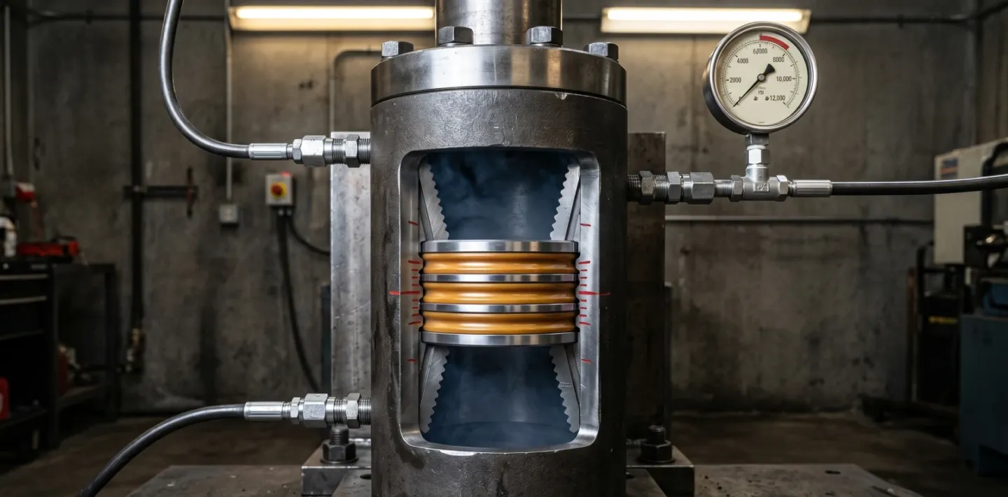
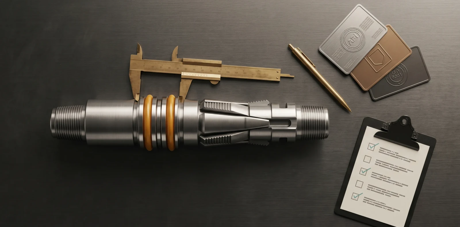
The series operates under API Q1, ISO 14310, and ISO 9001 quality systems, with material traceability documented from raw stock through finished assembly. Every shipment carries Mill Test Reports, inspection reports, and test certificates. The Vadodara facility houses an in-house test cell rated to 500°F and 15,000 PSI — exceeding standard product ratings.
SpectraMax Landing Nipples are available in L80, 9Cr, 13Cr, and P110 grades. Field deployment spans 200+ installations across India, the Middle East, and Southeast Asia.
Common Misconceptions About Landing Nipples
Three misconceptions surface most often in technical reviews — each has cost wireline trips.
First: that a landing nipple is a fitting like a plumbing nipple. The term "nipple" here refers to the short tubular form factor — a landing nipple is a precision-machined completion component with engineered seal bore, locking recess, and shoulder.
Second: that profile compatibility is generic — that any X mandrel fits any X nipple. Tubing size, weight class, and the manufacturer's exact seal bore ID must all match.
Third: that more selective nipples mean more flexibility. Each selective nipple adds an ID restriction — best practice is the minimum needed, with top-no-go RPT or RPTS for large-bore HPHT completions. If you need to explain this to non-technical stakeholders or procurement, the short version is: every nipple is a planned restriction.
Frequently Asked Questions
What is a landing nipple in oil and gas?
A landing nipple is a short, heavy-walled tubular run as part of the production tubing string, machined with an internal seal bore and a locking profile. It provides a precision landing point for wireline-deployed flow control devices — plugs, chokes, and subsurface safety valves. The term "nipple" refers to the short tubular form factor, not to plumbing fittings. Maximus OIGA manufactures landing nipples in the SpectraMax flow control series.
What is the difference between a selective and a no-go landing nipple?
A selective landing nipple allows multiple same-size nipples to coexist in one string, with the running tool determining where the lock seats — three selectivity methods are used: variable internal profile, running-tool actuation, and pre-spaced magnets. A no-go landing nipple has a reduced internal diameter that physically prevents the mandrel from passing, giving positive depth indication and a barrier against dropped tools. A common completion uses a string of selective X or R nipples with one XN or RN no-go at the bottom.
What is the function of a no-go landing nipple?
A no-go landing nipple performs two functions: positive seating indication (the lock mandrel cannot pass through the reduced internal diameter, so it must seat at this nipple) and barrier protection against wireline tools or dropped objects below the tubing string. Modern top-no-go variants such as Halliburton's RPT and RPTS allow the lock to seat on top of the polished bore, eliminating secondary ID restriction below — preferred for HPHT large-bore completions.
What materials are used for landing nipples in sour or HPHT service?
Landing nipple materials follow API Spec 5CT. Standard sweet service uses L80 Type 1. Mild CO2 or wet sour service moves to L80 9Cr or L80 13Cr, where chromium drives corrosion resistance. NACE MR0175 sour service typically uses the L80 family, with 13Cr selected where H2S partial pressure stays below 1.5 psi. P110 is used for high-strength deep sweet wells above 175°F. SpectraMax Landing Nipples are available across L80, 9Cr, 13Cr, and P110 grades with API 5CT material traceability and MTR documentation.
Next Steps
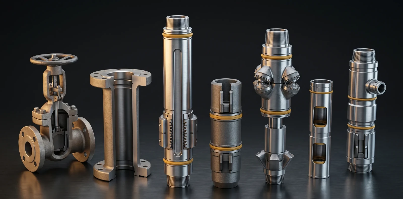
Landing nipples sit inside a wider flow control system — circulating sleeves, sliding sleeves, and the lock mandrels and plugs that engage them. Selecting the right profile, material grade, and selective-versus-no-go configuration is easier when the surrounding flow control architecture is built on the same engineering standards.
Related Blogs
More Information
Related News & Insights
ISO 14310 & API 11D1 Validation Grades: V6 to V0 Explained
Many engineers assume a higher V-number means a tougher packer. It is the opposite. Under ISO 14310 packer validation grades, the scale runs from V6, the minimum, down to V0, the most demanding gas-tight grade — so a lower number means more severe testing, not less. For anyone just trying to understand the basics, that inversion is where most confusion starts.
June 8, 2026
Intelligent Well Completion: Technologies, Market Trends & Equipment Guide
Imagine adjusting flow from each zone of a multi-zone reservoir in real time, from surface, without ever sending a rig downhole. That is the promise of intelligent well completion, and for an engineer just trying to understand the basics, the concept is more concrete than the marketing suggests once you see how the pieces connect.
June 8, 2026
Oil & Gas Equipment Companies in India: Manufacturer Directory 2026
Navigating India's oilfield equipment landscape is challenging without a comprehensive directory, and procurement teams asking "who are the best manufacturers for this?" often lose weeks to vendor research. This directory profiles the key oil and gas equipment companies in India with verified capabilities, so you can build a qualified shortlist faster.
June 8, 2026
Liner Hanger Types & Selection: Complete Engineering Reference
What type of liner hanger does your well design require? The answer depends on setting depth, liner weight, and whether hydraulic or mechanical actuation suits the hole. For an engineer just trying to understand the basics, the liner hanger types break down into three categories — and knowing how they differ is the first step toward specifying the right one.
June 6, 2026
Packer in Well Completion- Functions, Types & How to Select the Right One
Packers are installed in nearly every cased-hole completion worldwide, yet the packer in well completion remains one of the most consequential pieces of downhole hardware to understand. For anyone just trying to understand the basics, the packer is the component that makes controlled production possible by sealing the space between the tubing and the casing.
June 6, 2026
Swellable Packer Applications- Open Hole, HPHT & Water Shutoff Guide
When an operator needs to isolate an open hole section in a horizontal well without cementing, swellable packer applications offer the most direct route to a reliable annular seal. Across open hole zonal isolation, multistage fracturing, and water shutoff, the swellable packer has become the interventionless tool completion engineers reach for when running cement or mechanical packers is impractical or costly
June 6, 2026
How to Choose an Oilfield Equipment Supplier A Procurement Guide
Choosing the wrong oilfield equipment supplier does not just waste procurement budget; it risks downhole failures that cost ten times the equipment price. Knowing how to choose an oilfield equipment supplier means looking past the catalog and the quotation to the evidence that a vendor can actually deliver safety-critical completion equipment. Procurement engineers who get this right treat the decision as risk management, not purchasing
June 6, 2026
Top Downhole Tool Manufacturers & Suppliers 2026 Global Guide
The global downhole tools market exceeds 5 billion US dollars annually, and the list of companies claiming to serve it is far longer than any procurement team has time to vet. This guide narrows the field: it covers how to evaluate a downhole tool manufacturer, then profiles the global majors, the India-based OEMs, and Maximus OIGA — fairly, with real pros and cons, so you can build an RFQ shortlist without months of vendor research.
June 6, 2026
Sliding Sleeve Applications in Well Completion Types & Selection Guide
Sliding sleeves have evolved from simple open/close mechanisms into precision multi-zone flow control devices, and understanding their applications is now central to modern well completion design. This guide covers what a sliding sleeve does, the main types, real downhole applications, and how to select the right one — written for engineers trying to understand the basics and go a level deeper, not for a sales pitch.
June 6, 2026
Bridge Plug Setting Procedure Step-by-Step Guide for Wireline Operations
How do you properly set a bridge plug using wireline? This step-by-step procedure covers tool string assembly, depth correlation, setting tool activation, and pressure testing for confirmed well isolation. It is written for field engineers who need the exact sequence right the first time, with 200+ Maximus OIGA installations across India, the Middle East, and Southeast Asia behind it
June 6, 2026