Plug and Perf Completion: Equipment, Process & Selection Guide
Plug and perf completion is the dominant multistage hydraulic fracturing method for unconventional horizontal wells in North America, used in the majority of new horizontal well completions on the continent. The process uses a wireline-deployed bridge plug to isolate each stage of the lateral, followed by perforating guns to create casing entry points before the frac stage is pumped. Plugs are later milled out for production.
Plug and perf completion is the dominant multistage hydraulic fracturing method for unconventional horizontal wells in North America, used in the majority of new horizontal well completions on the continent. The process uses a wireline-deployed bridge plug to isolate each stage of the lateral, followed by perforating guns to create casing entry points before the frac stage is pumped. Plugs are later milled out for production.
This guide covers the four primary equipment categories, the six-step stage workflow, three persistent misconceptions, and the selection criteria engineers use when specifying plug and perf hardware.
Why Plug and Perf Matters
The U.S. horizontal-well share has more than doubled in a decade — from roughly 10% of producing wells in 2014 to about 22% in 2024 — and the Permian alone has been adding around 5,500 horizontal wells per year. Lateral lengths have grown with that share, with new wells routinely reaching 10,000 ft and some pushing past 20,000 ft. Each additional thousand feet of lateral typically means more frac stages, and each stage requires its own bridge plug.
Plug and perf is the method that scales with that geometry. It segments long horizontal laterals so individual zones can be treated separately, and it has remained the majority of new well completions in North America since unconventional development took off. A 2025 SPE study (SPE 227450) on tailored plug and perf optimization documented per-stage operational time reductions of up to 68% and non-productive time reductions above 25%.
Whether you are just trying to understand the basics or specifying equipment for an upcoming pad, the economics of an unconventional completion now hinge on plug performance and stage cycle time.
What Is Plug and Perf: Definition and Process Overview
If you need to explain plug and perf to non-technical stakeholders, the simplest version is this: a wireline lowers a small assembly into the horizontal section of a well, sets a plug to seal off the previous frac stage, then fires perforating guns to create new entry points in the casing for the next frac.
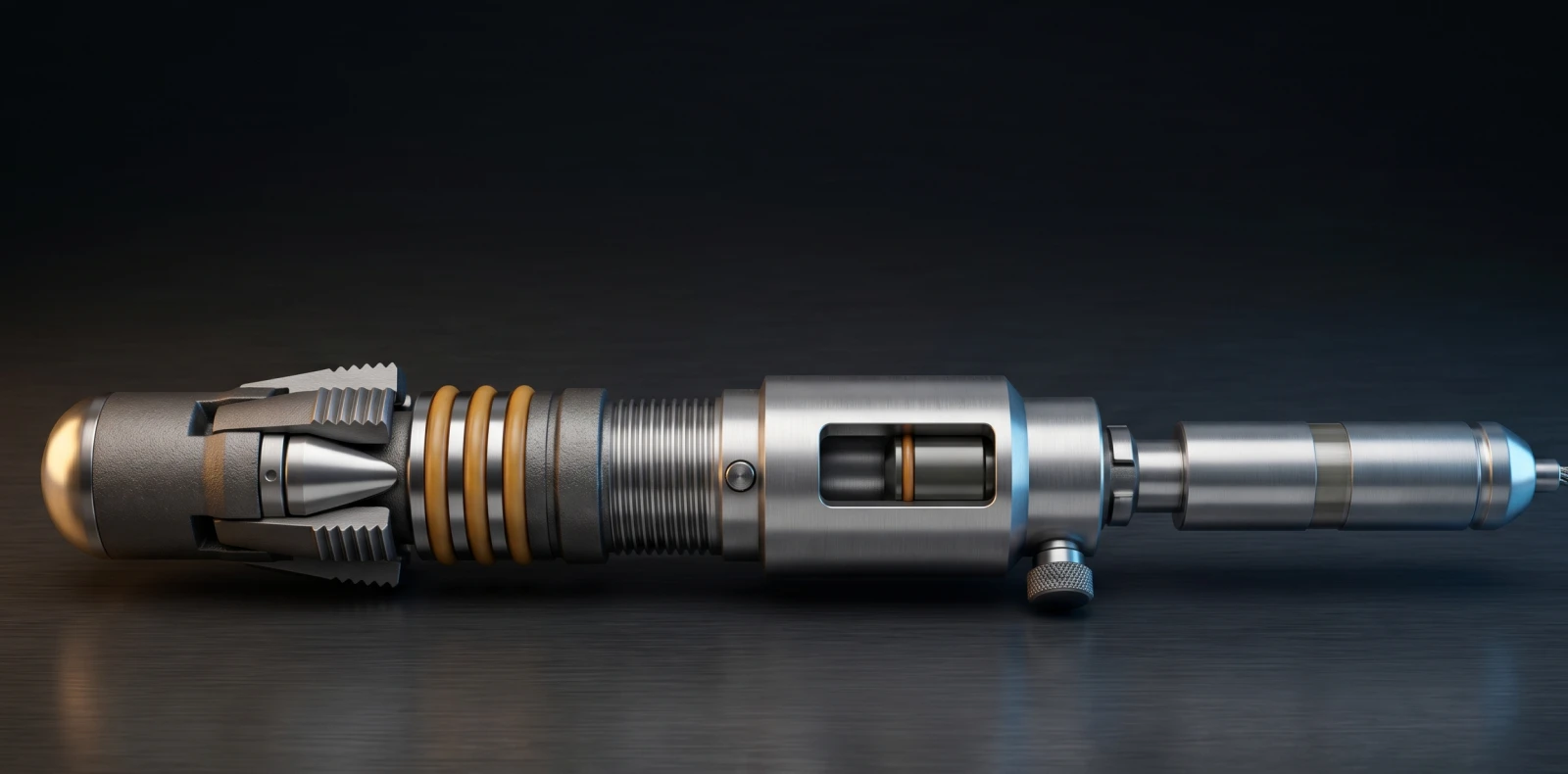
In a plug and perf operation, a wireline bottom-hole assembly (BHA) carrying a composite frac plug, setting tool, and perforating guns is pumped to a target depth in the cased horizontal lateral. The plug is set to isolate the previous stage; the guns then perforate the casing above the plug.
The bridge plug must stay anchored against the casing wall and gas-tight against differential pressure for the full duration of the frac that follows — typically minutes to hours of pumping at pressures up to 10,000 psi. Once the stage completes, the wireline is withdrawn, the next BHA is run, and the cycle repeats. A modern unconventional well can carry 30 or more stages.
Wireline plug and perf is the dominant conveyance method because it is faster and cheaper than coiled-tubing alternatives. After all stages are stimulated, the plugs are removed in a single milling run, and the well is brought online for production.
Equipment Used in Plug and Perf
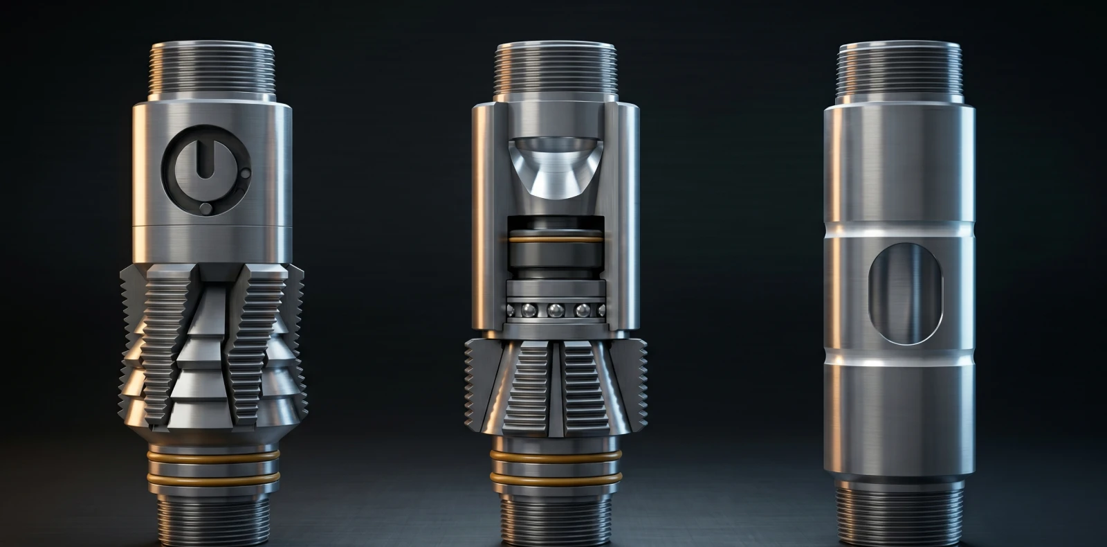
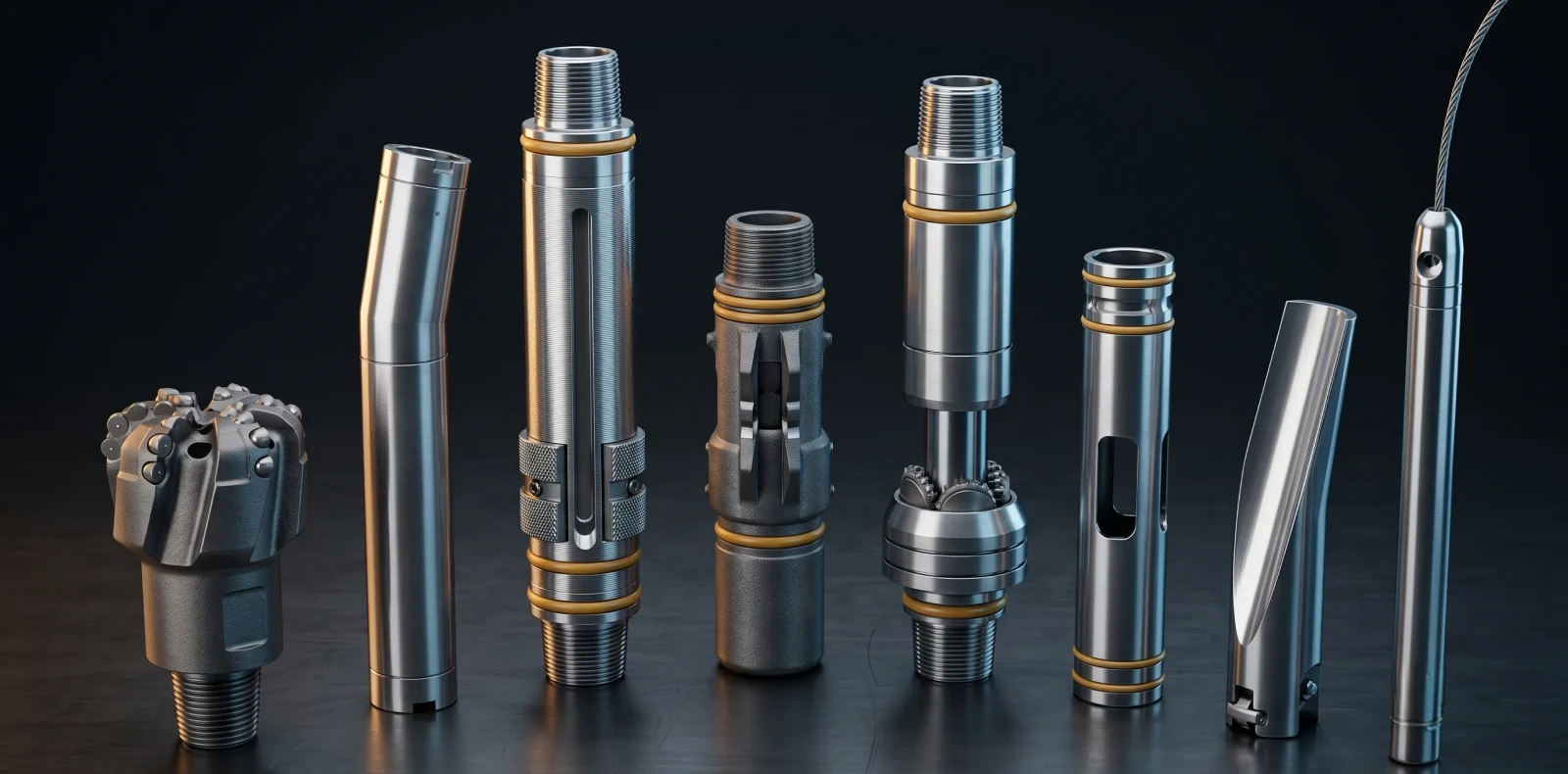
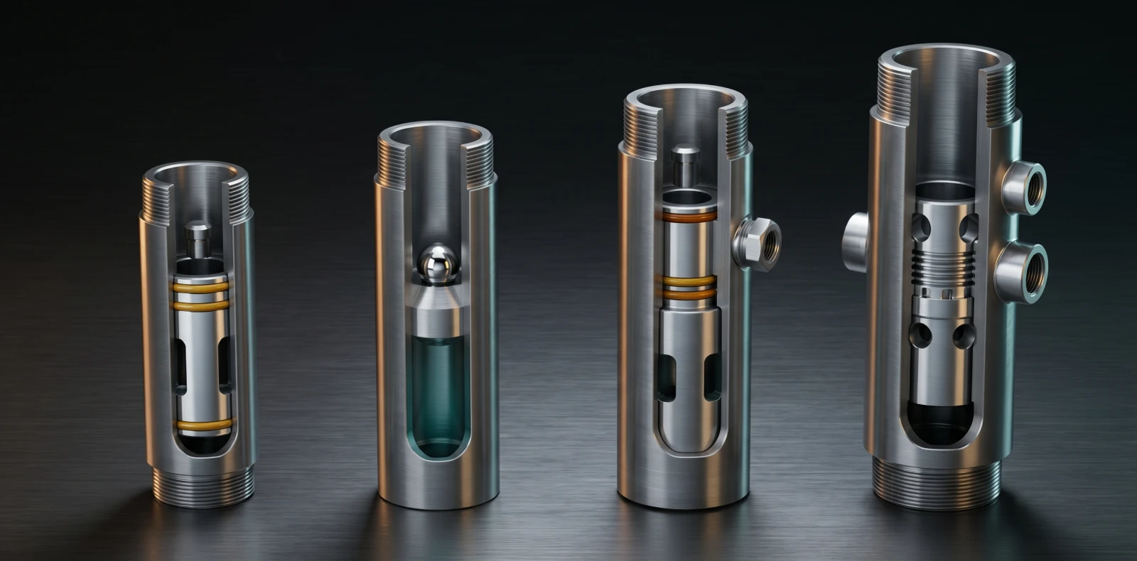
Plug and perf completions require four primary downhole equipment categories: composite or dissolvable frac plugs (rated to 10,000 psi differential), perforating guns with shaped charges, a wireline-conveyed setting tool, and the BHA assembly that carries them. Plugs and perforating guns must withstand pump-down forces and the high-pressure frac that follows isolation.
The frac plug is the centerpiece. Composite is the most common construction today, with cast-iron and dissolvable variants used where mill time, debris tolerance, or differential rating push the design in different directions. Maximus OIGA manufactures the cast-iron and composite bridge plug range used at the core of these BHAs — including the mandrel, upper and lower slips, cones, and the elastomer element. Element materials are typically HNBR or FKM, selected for the temperature and chemical environment of the target formation.
Perforating guns are shaped-charge cluster systems run on the wireline alongside the plug. Designs range from 4–6 clusters per stage on standard completions to 16 clusters per stage in high-density designs. The setting tool sits between the plug and the guns; it applies the design setting force to lock slips into the casing wall and energize the element. Cemented production casing is the wellbore environment plug and perf depends on — open-hole completions use packers instead.
| Equipment Item | Function | Typical Pressure Rating | Manufacturer Responsibility |
| Composite or dissolvable frac plug | Isolates the previous stage; holds pressure during the frac | 10,000 psi differential | Material strength of mandrel and lower cone; element compound; mill or dissolution profile |
| Perforating gun cluster | Creates casing entry points for the frac (4–16 clusters per stage) | Designed to shaped-charge spec; gun body to stage pressure | Charge selection, cluster spacing, gun body integrity |
| Wireline-conveyed setting tool | Applies setting force to lock slips and energize the element | Matched to plug design force | Setting force calibration, repeatability across runs |
| Cemented production casing | The wellbore environment plug and perf depends on | API casing rating per well design | Casing OD/ID tolerance verification before plug specification |
Plug and Perf Process: Stage-by-Stage Timeline
A plug and perf stage executes in six steps: (1) make up plug to BHA at surface, (2) pump BHA down the lateral on wireline, (3) set the bridge plug to isolate the prior stage, (4) perforate the casing above the plug, (5) retrieve wireline and pump the frac, and (6) repeat per stage, then mill plugs.
The plug and perf frac method now lives or dies on how cleanly that cycle runs. The six steps below describe a single stage from surface make-up through stimulation; multiply by the stage count for the full lateral.
Step 1 — Make up plug to BHA at surface. The plug is connected to the setting tool with proper torque so the design setting force is exerted. Errors here propagate downhole as failed sets.
Step 2 — Run-in-hole. The wireline runs the BHA through the vertical section. Once in the lateral, surface pumps push fluid behind the assembly to carry it horizontally to target depth.
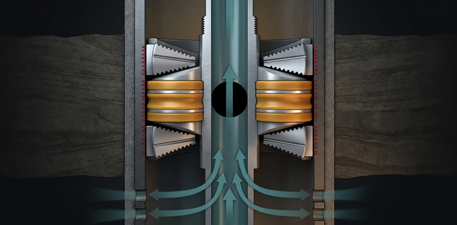
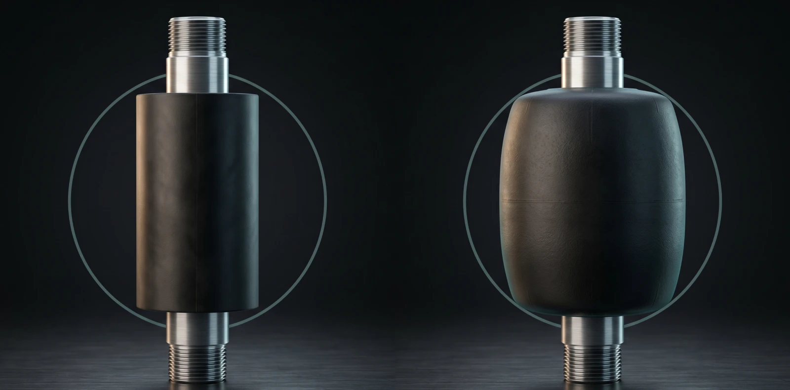
Step 3 — Set the bridge plug. The setting tool applies force to lock slips into the casing wall and compress the element against the casing ID, isolating the previous stage.
Step 4 — Perforate the casing. Guns fire shaped charges through casing, cement, and into the formation. Designs typically run 4–6 clusters per stage, with some up to 16.
Step 5 — Retrieve wireline and pump the frac. Surface frac equipment rigs up. A ball is dropped to seat on the plug, the seal isolates fully, and treatment fluid plus proppant is pumped at design rate — pressures up to 10,000 psi.
Step 6 — Repeat per stage; mill out plugs after the frac is complete. Composite plugs typically mill in 5–10 minutes apiece. Dissolvable plugs eliminate the mill-out run entirely.
Need expert guidance on the right solution?
Talk to our engineers about your project requirements.
Why Maximus OIGA: Manufacturer Authority
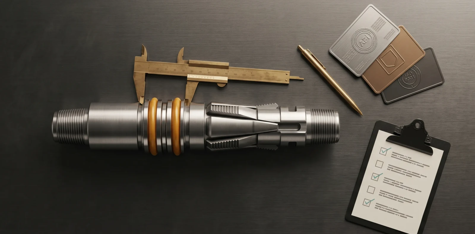
Maximus OIGA is a Vadodara-headquartered well completion equipment manufacturer specializing in downhole tools — packers, bridge plugs, flow control, and liner hangers. The company holds API Q1, ISO 14310, and ISO 9001 certifications, and operates an in-house test facility that issues material traceability records and witnessed test certificates with every shipment.
More than 200 installations across India, the Middle East, and Southeast Asia sit behind that documentation. For plug and perf operations, Maximus OIGA bridge plug systems cover both cast-iron and composite construction across the differential ratings, mill profiles, and casing sizes used in unconventional completions.
The depth-over-breadth positioning matters here. Plug and perf cycle times collapse when the plug fails to set, blows through during pump-down, or mills slowly. The team specifying the equipment has more leverage with a manufacturer that builds the plug than with a generalist supplier sourcing it.
Common Misconceptions About Plug and Perf
Three misconceptions persist in conversations about plug and perf hardware — usually from teams pulling specifications from older completion designs.
Misconception 1: A bridge plug is the same as a packer. Both isolate, but bridge plugs in plug-and-perf service are typically temporary — composite or dissolvable, milled or dissolved out before production. Packers are designed to remain in the well as part of the production string. The design intents diverge: plug = isolate-then-remove; packer
= isolate-and-stay.
Misconception 2: Plug and perf is being replaced by sliding sleeves. Sliding sleeve completions exist and are selected on specific designs, but plug and perf still dominates U.S. unconventional completions per Baker Hughes. The two methods serve different design philosophies — perf and plug optimizes stage placement flexibility, sliding sleeves optimize cycle time.
Misconception 3: All composite frac plugs mill the same way. Plug failure during pump-down or pressure ramp is most often caused by collapse of the lower cone or mandrel, and the strength of those components varies significantly between manufacturers. Mill-time advertised on a spec sheet is only meaningful when the plug actually held through the frac.
FAQ
Q1. What is the plug and perf method?
Plug and perf is a multistage hydraulic fracturing completion method in which a wireline-deployed bridge plug isolates each lateral stage and a perforating gun creates entry points for the frac. The plug holds pressure during stimulation, then is milled out before the well is brought online for production. A modern horizontal well can carry 30 or more stages and an equivalent number of plugs.
Q2. What equipment is used in plug and perf?
Plug and perf equipment falls into six categories: a frac or bridge plug (composite or dissolvable, pressure-rated to 10,000 psi) that isolates each stage; a perforating gun cluster that fires shaped charges through the casing; a wireline and setting tool that conveys the BHA, energizes the element, and locks the slips; the BHA assembly that connects all three into a single run; surface frac equipment for the stimulation phase; and cemented production casing as the wellbore environment. Maximus OIGA manufactures the at the core of this BHA.
Q3. What is the difference between plug and perf and sliding sleeve completions?
Plug and perf vs sliding sleeve comes down to flexibility versus cycle time. Plug and perf runs in cemented liner; each stage is isolated by a wireline-set bridge plug, giving operators maximum flexibility on stage placement — at the cost of multiple wireline runs and a milling operation. Sliding sleeves are pre-installed in the liner and opened by ball-drop or remote actuation; they are faster between stages but constrain placement to the sleeve positions designed before the well was run. Plug and perf still dominates U.S. unconventional completions per Baker Hughes.
Q4. What should I know before specifying plug and perf equipment?
Five specifications drive the selection. Pressure rating — match the plug differential rating to maximum frac pressure with margin (typical: 10,000 psi class). Casing size and weight — the plug OD must match the casing drift ID, verified against the manufacturer tally. Mill time or dissolution profile — composite plugs mill in 5–10 minutes; dissolvable plugs eliminate the mill-out run. Certification — verify API Q1 manufacturing system documentation and, where applicable, ISO 14310 V0 sealing class. Manufacturer test data — request material traceability and witnessed test certificates. Maximus OIGA provides API Q1 documentation with every bridge plug shipment.
Next Steps
Specifying plug and perf completion hardware comes down to two product families: the bridge plug at the core of every stage, and the packers used where non-cemented isolation is the right design.
To request specifications, certification documentation, or a casing-size tally for an upcoming program, contact the Maximus OIGA engineering team at exports.
Related Blogs
More Information
Related News & Insights
ISO 14310 & API 11D1 Validation Grades: V6 to V0 Explained
Many engineers assume a higher V-number means a tougher packer. It is the opposite. Under ISO 14310 packer validation grades, the scale runs from V6, the minimum, down to V0, the most demanding gas-tight grade — so a lower number means more severe testing, not less. For anyone just trying to understand the basics, that inversion is where most confusion starts.
June 8, 2026
Intelligent Well Completion: Technologies, Market Trends & Equipment Guide
Imagine adjusting flow from each zone of a multi-zone reservoir in real time, from surface, without ever sending a rig downhole. That is the promise of intelligent well completion, and for an engineer just trying to understand the basics, the concept is more concrete than the marketing suggests once you see how the pieces connect.
June 8, 2026
Oil & Gas Equipment Companies in India: Manufacturer Directory 2026
Navigating India's oilfield equipment landscape is challenging without a comprehensive directory, and procurement teams asking "who are the best manufacturers for this?" often lose weeks to vendor research. This directory profiles the key oil and gas equipment companies in India with verified capabilities, so you can build a qualified shortlist faster.
June 8, 2026
Liner Hanger Types & Selection: Complete Engineering Reference
What type of liner hanger does your well design require? The answer depends on setting depth, liner weight, and whether hydraulic or mechanical actuation suits the hole. For an engineer just trying to understand the basics, the liner hanger types break down into three categories — and knowing how they differ is the first step toward specifying the right one.
June 6, 2026
Packer in Well Completion- Functions, Types & How to Select the Right One
Packers are installed in nearly every cased-hole completion worldwide, yet the packer in well completion remains one of the most consequential pieces of downhole hardware to understand. For anyone just trying to understand the basics, the packer is the component that makes controlled production possible by sealing the space between the tubing and the casing.
June 6, 2026
Swellable Packer Applications- Open Hole, HPHT & Water Shutoff Guide
When an operator needs to isolate an open hole section in a horizontal well without cementing, swellable packer applications offer the most direct route to a reliable annular seal. Across open hole zonal isolation, multistage fracturing, and water shutoff, the swellable packer has become the interventionless tool completion engineers reach for when running cement or mechanical packers is impractical or costly
June 6, 2026
How to Choose an Oilfield Equipment Supplier A Procurement Guide
Choosing the wrong oilfield equipment supplier does not just waste procurement budget; it risks downhole failures that cost ten times the equipment price. Knowing how to choose an oilfield equipment supplier means looking past the catalog and the quotation to the evidence that a vendor can actually deliver safety-critical completion equipment. Procurement engineers who get this right treat the decision as risk management, not purchasing
June 6, 2026
Top Downhole Tool Manufacturers & Suppliers 2026 Global Guide
The global downhole tools market exceeds 5 billion US dollars annually, and the list of companies claiming to serve it is far longer than any procurement team has time to vet. This guide narrows the field: it covers how to evaluate a downhole tool manufacturer, then profiles the global majors, the India-based OEMs, and Maximus OIGA — fairly, with real pros and cons, so you can build an RFQ shortlist without months of vendor research.
June 6, 2026
Sliding Sleeve Applications in Well Completion Types & Selection Guide
Sliding sleeves have evolved from simple open/close mechanisms into precision multi-zone flow control devices, and understanding their applications is now central to modern well completion design. This guide covers what a sliding sleeve does, the main types, real downhole applications, and how to select the right one — written for engineers trying to understand the basics and go a level deeper, not for a sales pitch.
June 6, 2026
Bridge Plug Setting Procedure Step-by-Step Guide for Wireline Operations
How do you properly set a bridge plug using wireline? This step-by-step procedure covers tool string assembly, depth correlation, setting tool activation, and pressure testing for confirmed well isolation. It is written for field engineers who need the exact sequence right the first time, with 200+ Maximus OIGA installations across India, the Middle East, and Southeast Asia behind it
June 6, 2026