Circulating Sleeve vs Sliding Sleeve: When to Use Which in Well Completion
Circulating sleeves enable fluid circulation during cementing and intervention; sliding sleeves control selective zone production over the well's life. The circulating sleeve vs sliding sleeve question comes down to one engineering reality — your completion design determines which you need, and most multi-zone wells specify both. What's the difference and which one do I need? The answer turns on three variables: primary use case, cycle frequency, and well architecture.
Circulating sleeves enable fluid circulation during cementing and intervention; sliding sleeves control selective zone production over the well's life. The circulating sleeve vs sliding sleeve question comes down to one engineering reality — your completion design determines which you need, and most multi-zone wells specify both. What's the difference and which one do I need? The answer turns on three variables: primary use case, cycle frequency, and well architecture.
three variables: primary use case, cycle frequency, and well architecture.
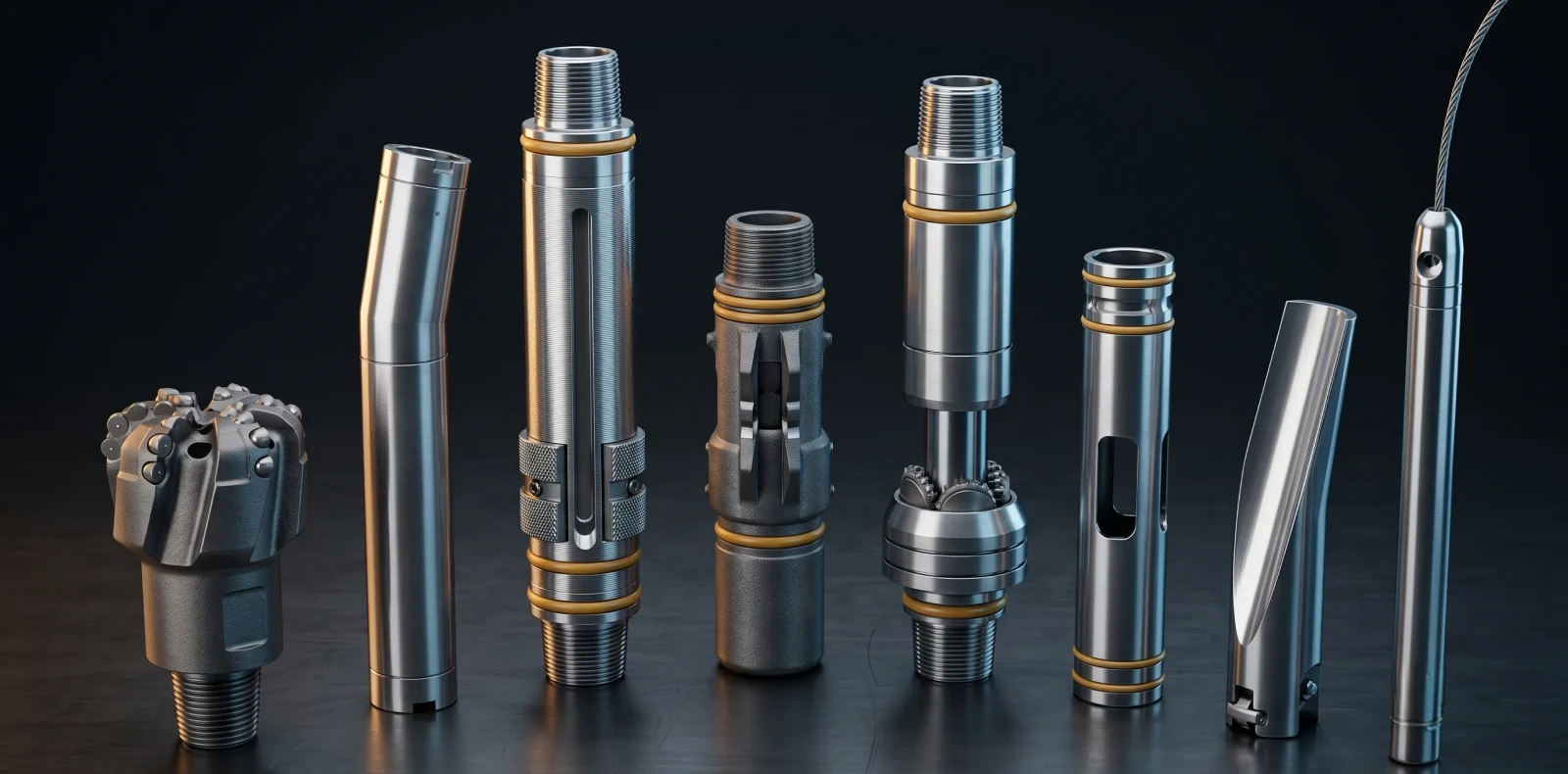
Circulating sleeves and sliding sleeves both establish communication between production tubing and the casing annulus, but they serve different primary functions. Circulating sleeves are optimized for fluid displacement during well completion and intervention; sliding sleeves (also called Sliding Side Doors or SSDs) control selective zone production and long-term flow management.
Circulating Sleeve vs Sliding Sleeve: Specification Comparison
The table below sets the two devices side by side across the criteria a completion engineer evaluates before specification. Both are non-drillable and remain permanent in the tubing string — what separates them is operating intent.
| Criteria | Circulating Sleeve | Sliding Sleeve (SSD) |
| Primary Purpose | Fluid circulation, displacement, equalization | Selective zone production and flow control |
| Typical Use Frequency | Few cycles (completion + interventions) | Repeated cycling over well's production life |
| Actuation Mechanism | Wireline (Model B shifting tool — jarring) | Wireline, coiled tubing, or hydraulic (control line) |
| Temperature Rating (typical) | Up to 300°F (149°C) standard; higher with premium elastomers | Up to 375°F (191°C) with non-elastomeric seals |
| Pressure Rating (typical) | 5,000–10,000 PSI depending on configuration | Up to 10,000 PSI (68,948 kPa) on non-elastomeric designs |
| Common Materials | AISI 4140/4130, 13Cr, Inconel for sour service | 13Cr martensitic stainless, Super 13Cr, Inconel 718 for sour/HPHT |
| Seal Type | Elastomer packing (HNBR); non-elastomeric for HT | Non-elastomeric (ECM/DURATEF) increasingly standard |
| Typical Applications | Cementing displacement, well killing, chemical injection | Multi-zone production, gas lift, commingled production |
| Drillability | Non-drillable (permanent in tubing string) | Non-drillable (permanent in tubing string) |
| Cost Positioning | Typically lower — simpler actuation requirement | Higher — modular design, multiple shift directions, SS materials |
| Maximus OIGA Product | SpectraMax circulating sleeves | SpectraMax sliding sleeves |
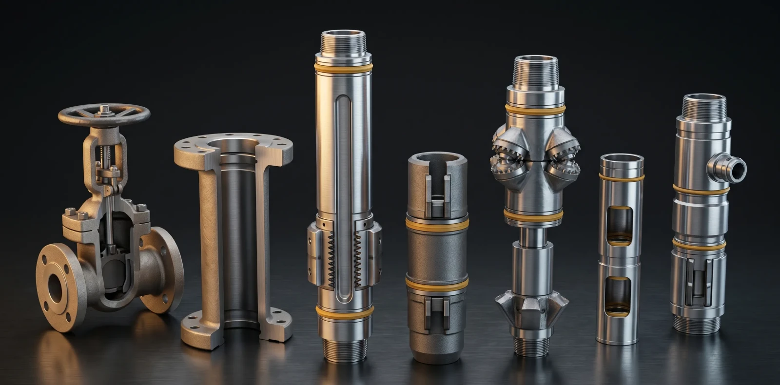
For the broader product family covering both sleeve types alongside chokes, valves, and landing nipples, see the flow control equipment manufacturer overview.
Circulating Sleeve: How It Works, Specifications, and Applications
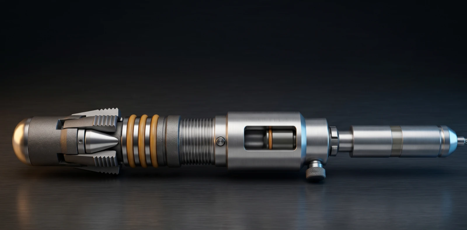
A circulating sleeve is a downhole flow control device screwed into the production tubing with ports that open or close via a wireline-operated Model B shifting tool. Maximus OIGA circulating sleeves support fluid displacement, well killing, pressure equalization, chemical injection, and selective zone testing across completion and intervention stages.
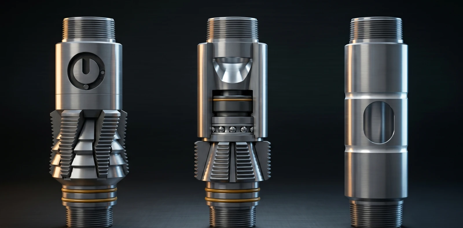
How It Works
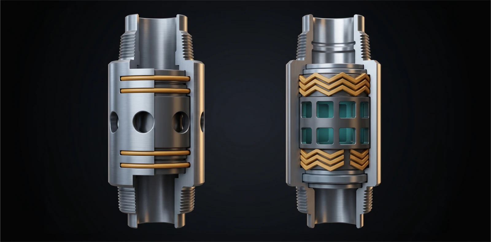
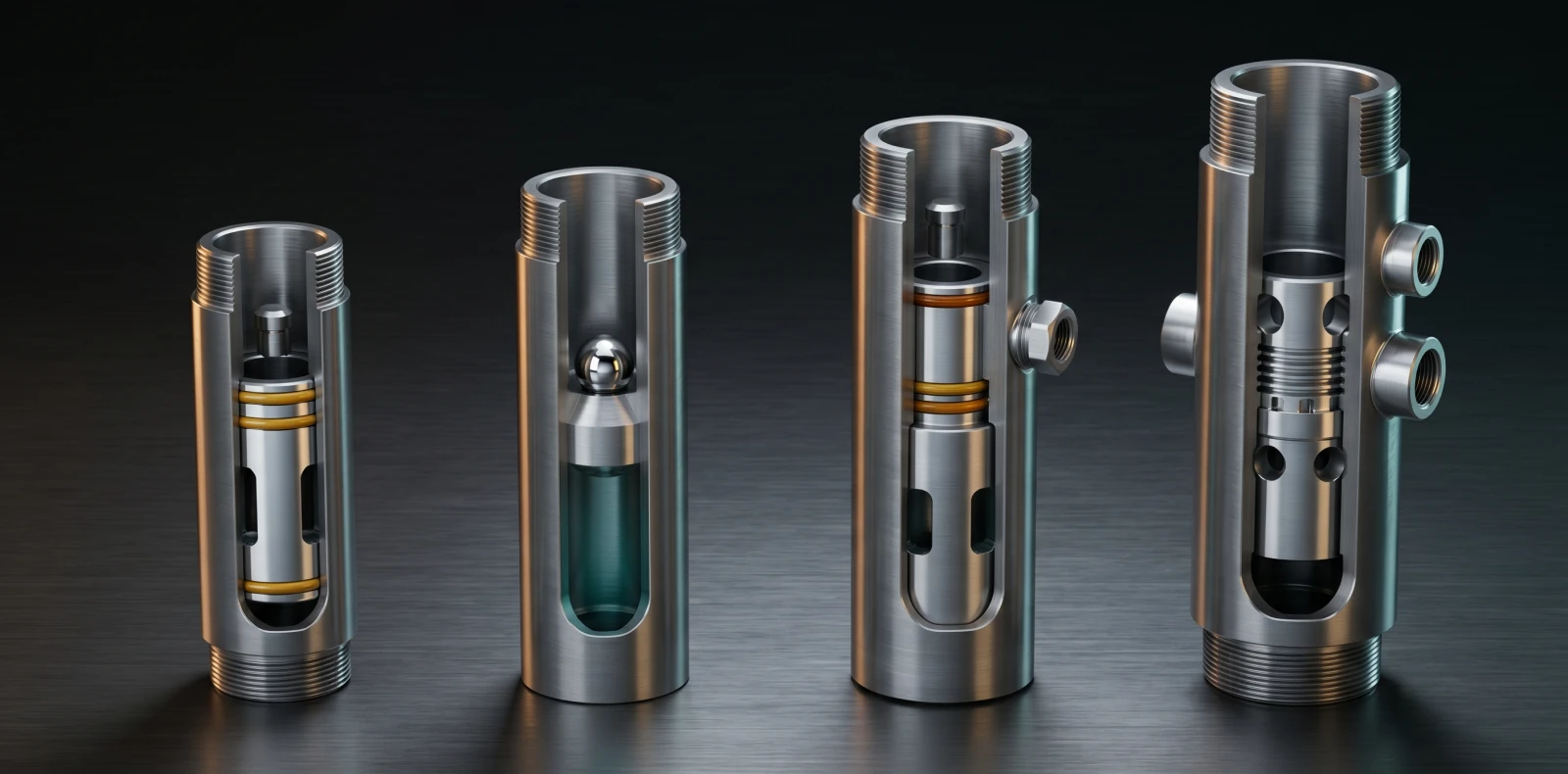
A circulating sleeve consists of a top sub with a landing nipple profile, an outer housing with circulation ports, an inner ported sleeve with seal packings above and below the ports, and a bottom sub. The inner sleeve shifts between open and closed positions; the packings prevent flow when closed. Actuation uses a Model B shifting tool on slickline — downward jarring opens XO-type sleeves; upward jarring opens XD/XA-type sleeves.
Typical Specifications
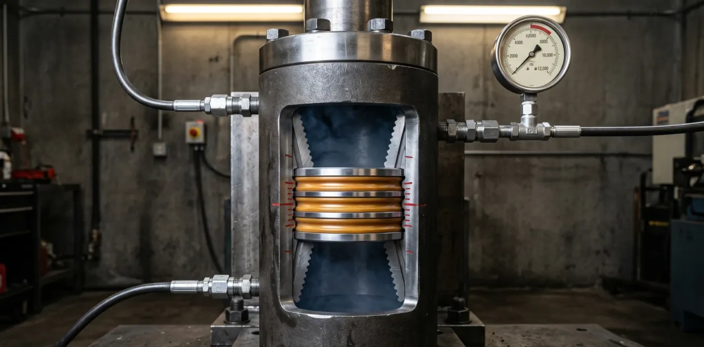
Standard circulating sleeves are rated to 5,000–10,000 PSI and operate to 300°F (149°C) on HNBR elastomer packing. Higher-temperature builds use premium elastomers or non-elastomeric seal stacks. Body materials run from AISI 4140/4130 for sweet service to 13Cr and Inconel grades for sour and HPHT service. Industry comparators include MAP MXO/MXD/MXA, GRIFCO XO/XA, and the Maximus OIGA SpectraMax circulating sleeve series.
Pros and Cons
A single shifting-tool run opens or closes the ports — multiple communication events without pulling tubing. Construction is mechanically simpler than hydraulically actuated alternatives, which keeps unit cost lower and field-service straightforward. Limitations: wireline intervention is required for every actuation cycle unless a hydraulic variant is specified, elastomer-sealed designs degrade above 300°F and in aggressive H₂S service, and the device is non-drillable.
Ideal Applications
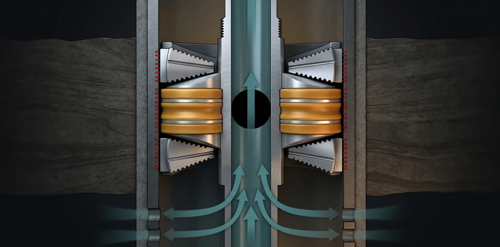
Circulating sleeves are specified for fluid displacement during completion, well killing via circulation before pulling out of hole, pressure equalization across packers, chemical or inhibitor injection, selective zone testing, and gas-lift kick-off. The common thread is event-driven use — a few planned actuations rather than continuous production cycling.
For SpectraMax specifications and seal-stack configurations, see the Maximus OIGA circulating sleeve manufacturer
Sliding Sleeve (SSD): How It Works, Specifications, and Applications
How It Works
A sliding sleeve incorporates a system of ports that can be opened or closed by a sliding inner component, controlled by a slickline tool string — as defined by the SLB Energy Glossary definition of sliding sleeve Two functional categories exist: open/close designs for binary port control, and choking designs that are hydraulically actuated for adjustable flow. Actuation options span wireline and slickline, coiled tubing for deviated wells, hydraulic control lines, pressure darts, and differential annulus pressure.
Typical Specifications
Major industry products include SLB AS-3 and CS-series; Halliburton DuraSleeve with DURATEF ECM seals; Baker Hughes CMD (downshift-to-open) and CMU (upshift-to-open) non-elastomeric models; and Weatherford OptiSleeve, rated to 375°F (191°C) and 10,000 PSI. Required opening force is typically a few hundred PSI of differential plus 10,000+ lb of shifting force. SSDs should be spaced at least 10 m (30 ft) apart in the tubing string to prevent accidental operation of adjacent components.
Pros and Cons
Selective zone production can be reconfigured over the well's life without pulling tubing, casing remains intact compared with plug-and-perf alternatives, and zones can be selectively re-intervened. Newer ECM/DURATEF-class non-elastomeric seal designs extend service life and reduce the annulus-leak risk historically associated with SSDs above the production packer. Limitations: modular construction with multiple shift directions and stainless or nickel-alloy materials makes SSDs more expensive on a unit basis, and repeated cycling over years can introduce scale and debris into the seal area, raising required shifting force.
Ideal Applications
Sliding sleeves are specified for selective-zone production in multi-zone wells, commingled production, gas lift operations, pressure equalization, well unloading after workover, and as a reclosable alternative to plug-and-perf in shale stimulation. The common thread is repeated cycling over the producing life of the well rather than event-driven intervention.
For SpectraMax SSD specifications, including non-elastomeric seal options, see the Maximus OIGA sliding sleeve manufacturer.
Need expert guidance on the right solution?
Talk to our engineers about your project requirements.
Which Sleeve Is Right for Your Well? A Selection Framework
The sliding sleeve oil and gas selection question rarely has a single answer — most multi-zone production strings carry both. The framework below resolves the choice across four operating variables. Which performs better in your specific HPHT, sour-service, deviated, or multi-zone condition? Apply the axes in order.
If your primary need is fluid circulation during completion or intervention
Specify a circulating sleeve. Cementing displacement, well killing, pressure equalization across packers, and chemical injection are event-driven operations. The simpler actuation requirement keeps unit cost down without sacrificing reliability for the duty cycle. For a procurement review, the cost-per-completion-cycle math favors a circulating sleeve when the spec sheet shows fewer than 10 expected lifetime actuations.
If your primary need is regulating selective zone production over the well's life
Specify a sliding sleeve. Multi-zone wells managing water cut, pressure depletion, or commingled production over years require a device built for repeated cycling. Non-elastomeric seal designs are the current standard above the production packer where annulus-leak risk must be controlled.
If sustained operating temperature exceeds 350°F (177°C)
Specify a sliding sleeve with non-elastomeric seals. Proven designs operate to 375°F (191°C) and 10,000 PSI.
If your well is multi-zone with both completion and life-of-well requirements
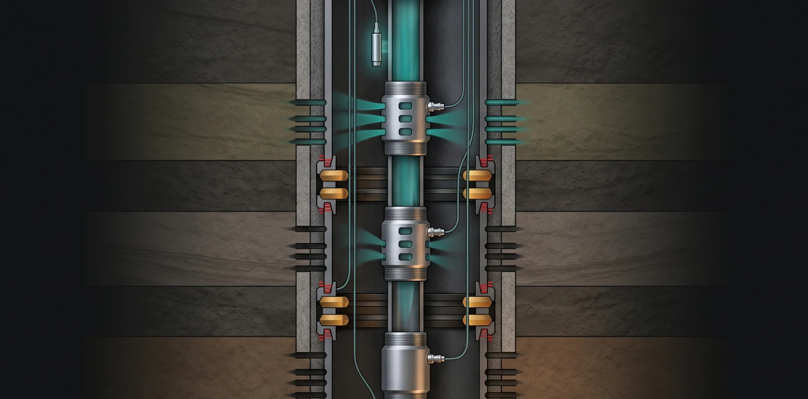
Specify both. Typical architecture places a circulating sleeve at cementing-displacement depth and a sliding sleeve at each producing zone, isolated by packers. Sourcing both from a single manufacturer simplifies traceability and field-service support across the completion.
Frequently Asked Questions
What is the difference between a circulating sleeve and a sliding sleeve?
Both establish communication between production tubing and the casing annulus through a ported inner sleeve, and both are typically actuated with a Model B shifting tool. The difference is primary function. Circulating sleeves are optimized for fluid circulation events — cementing displacement, well killing, chemical injection — and are specified for a few cycles. Sliding sleeves (SSDs) are optimized for selective zone production control and are designed for repeated cycling. Several manufacturers sell combined sliding/circulating designs, which underscores that the distinction is about primary use case rather than always being a fundamentally different device.
What is SSD in drilling and well completion?
SSD stands for Sliding Side Door — an alternate industry name for a sliding sleeve. It provides controlled communication between the tubing and the casing annulus through a ported sliding inner sleeve. SSDs are installed in the tubing string during completion and are actuated by wireline shifting tools, coiled tubing in deviated wells, hydraulic control lines, pressure darts, or differential annulus pressure. Typical applications: fluid displacement, well killing, gas lift, selective zone testing, chemical injection, and pressure equalization. Standard placement rule: at least 10 m (30 ft) between adjacent SSDs to prevent accidental actuation when a shifting tool is run.
Which sleeve performs better in multi-zone wells?
Sliding sleeves are the standard choice for multi-zone wells. Each producing zone receives its own sliding sleeve installed between isolating packers, and operators selectively open or close zones to manage water cut, pressure depletion, or commingled production. Circulating sleeves are supplementary — typically one at a deeper position to enable a well-kill or displacement operation across the entire string. Maximus OIGA supplies the complete string — packers, sliding sleeves, circulating sleeves, and landing nipples — from a single integrated product line.
Can a circulating sleeve and a sliding sleeve be used in the same well?
Yes — and in most multi-zone production wells, both are used together. The standard configuration places one circulating sleeve at a position selected for well-kill and displacement operations, with multiple sliding sleeves (one per producing zone) positioned for long-term flow management. The two device types serve different needs in the same string, so specifying both is not functional redundancy. Sourcing both from a single manufacturer simplifies procurement and ensures consistent material traceability across the completion.
Specify the Right Sleeve for Your Well
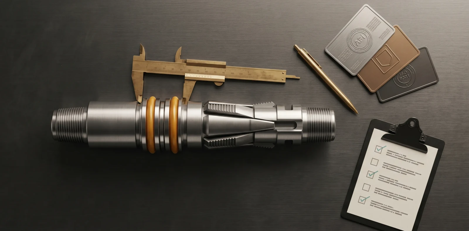
Your well conditions determine which sleeve — let our completion engineers review your specs. Maximus OIGA manufactures both SpectraMax circulating sleeves and SpectraMax sliding sleeves under the same API Q1 + ISO 14310 + ISO 9001 quality system, with material traceability and inspection certificates supplied with every shipment.
Related Blogs
More Information
Related News & Insights
ISO 14310 & API 11D1 Validation Grades: V6 to V0 Explained
Many engineers assume a higher V-number means a tougher packer. It is the opposite. Under ISO 14310 packer validation grades, the scale runs from V6, the minimum, down to V0, the most demanding gas-tight grade — so a lower number means more severe testing, not less. For anyone just trying to understand the basics, that inversion is where most confusion starts.
June 8, 2026
Intelligent Well Completion: Technologies, Market Trends & Equipment Guide
Imagine adjusting flow from each zone of a multi-zone reservoir in real time, from surface, without ever sending a rig downhole. That is the promise of intelligent well completion, and for an engineer just trying to understand the basics, the concept is more concrete than the marketing suggests once you see how the pieces connect.
June 8, 2026
Oil & Gas Equipment Companies in India: Manufacturer Directory 2026
Navigating India's oilfield equipment landscape is challenging without a comprehensive directory, and procurement teams asking "who are the best manufacturers for this?" often lose weeks to vendor research. This directory profiles the key oil and gas equipment companies in India with verified capabilities, so you can build a qualified shortlist faster.
June 8, 2026
Liner Hanger Types & Selection: Complete Engineering Reference
What type of liner hanger does your well design require? The answer depends on setting depth, liner weight, and whether hydraulic or mechanical actuation suits the hole. For an engineer just trying to understand the basics, the liner hanger types break down into three categories — and knowing how they differ is the first step toward specifying the right one.
June 6, 2026
Packer in Well Completion- Functions, Types & How to Select the Right One
Packers are installed in nearly every cased-hole completion worldwide, yet the packer in well completion remains one of the most consequential pieces of downhole hardware to understand. For anyone just trying to understand the basics, the packer is the component that makes controlled production possible by sealing the space between the tubing and the casing.
June 6, 2026
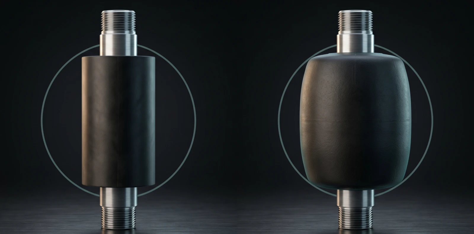
Swellable Packer Applications- Open Hole, HPHT & Water Shutoff Guide
When an operator needs to isolate an open hole section in a horizontal well without cementing, swellable packer applications offer the most direct route to a reliable annular seal. Across open hole zonal isolation, multistage fracturing, and water shutoff, the swellable packer has become the interventionless tool completion engineers reach for when running cement or mechanical packers is impractical or costly
June 6, 2026
How to Choose an Oilfield Equipment Supplier A Procurement Guide
Choosing the wrong oilfield equipment supplier does not just waste procurement budget; it risks downhole failures that cost ten times the equipment price. Knowing how to choose an oilfield equipment supplier means looking past the catalog and the quotation to the evidence that a vendor can actually deliver safety-critical completion equipment. Procurement engineers who get this right treat the decision as risk management, not purchasing
June 6, 2026
Top Downhole Tool Manufacturers & Suppliers 2026 Global Guide
The global downhole tools market exceeds 5 billion US dollars annually, and the list of companies claiming to serve it is far longer than any procurement team has time to vet. This guide narrows the field: it covers how to evaluate a downhole tool manufacturer, then profiles the global majors, the India-based OEMs, and Maximus OIGA — fairly, with real pros and cons, so you can build an RFQ shortlist without months of vendor research.
June 6, 2026
Sliding Sleeve Applications in Well Completion Types & Selection Guide
Sliding sleeves have evolved from simple open/close mechanisms into precision multi-zone flow control devices, and understanding their applications is now central to modern well completion design. This guide covers what a sliding sleeve does, the main types, real downhole applications, and how to select the right one — written for engineers trying to understand the basics and go a level deeper, not for a sales pitch.
June 6, 2026
Bridge Plug Setting Procedure Step-by-Step Guide for Wireline Operations
How do you properly set a bridge plug using wireline? This step-by-step procedure covers tool string assembly, depth correlation, setting tool activation, and pressure testing for confirmed well isolation. It is written for field engineers who need the exact sequence right the first time, with 200+ Maximus OIGA installations across India, the Middle East, and Southeast Asia behind it
June 6, 2026