Cement Retainer vs Bridge Plug-When to Use Which for Well Isolation
Many completion engineers treat cement retainers and bridge plugs as interchangeable isolation tools. In practice, they serve fundamentally different functions in well abandonment, squeeze cementing, and zonal isolation — and choosing the wrong one introduces equipment failure risk, milling delays, and barrier-verification rework.
Many completion engineers treat cement retainers and bridge plugs as interchangeable isolation tools. In practice, they serve fundamentally different functions in well abandonment, squeeze cementing, and zonal isolation — and choosing the wrong one introduces equipment failure risk, milling delays, and barrier-verification rework.
VERDICT — At a Glance For controlled cement injection, choose a cement retainer. For a sealed pressure barrier, choose a bridge plug. In plug and abandonment, both are used together. |
| Manufacturer of cement retainers and bridge plugs to API 11D1 / ISO 14310 — request specs. |
Cement Retainer vs Bridge Plug Specification Comparison
Cement retainer vs bridge plug specification comparison
| Criteria | Cement Retainer | Bridge Plug |
|---|---|---|
| Primary Function | Cement placement control and backflow prevention | Wellbore barrier and zonal isolation |
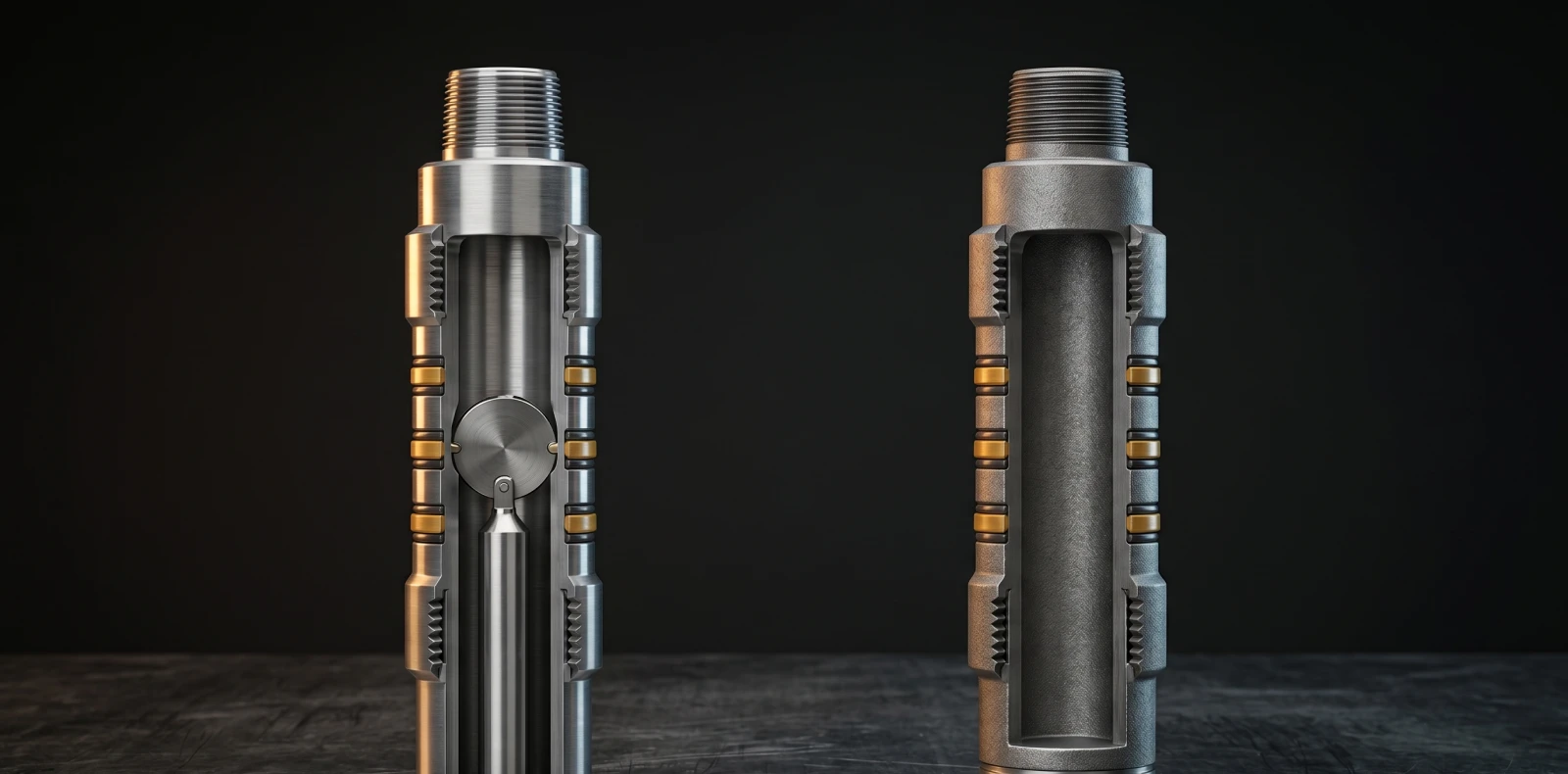
| Flow Path | Integrated valve — opens under stinger insertion, closes on stinger removal | None — sealed mandrel |
| Construction Material | Cast iron (typical), compact for drillout | Cast iron (permanent) or composite (retrievable / drillable) |
| Setting Method | Wireline (slow-burning charge), drillpipe/tubing (rotation), coiled tubing | Wireline, slickline, tubing, coiled tubing |
| Retrievable? | Drillable — drilled out after the squeeze | Both options — permanent (drilled out) or retrievable (mechanical, GS pulling tool) |
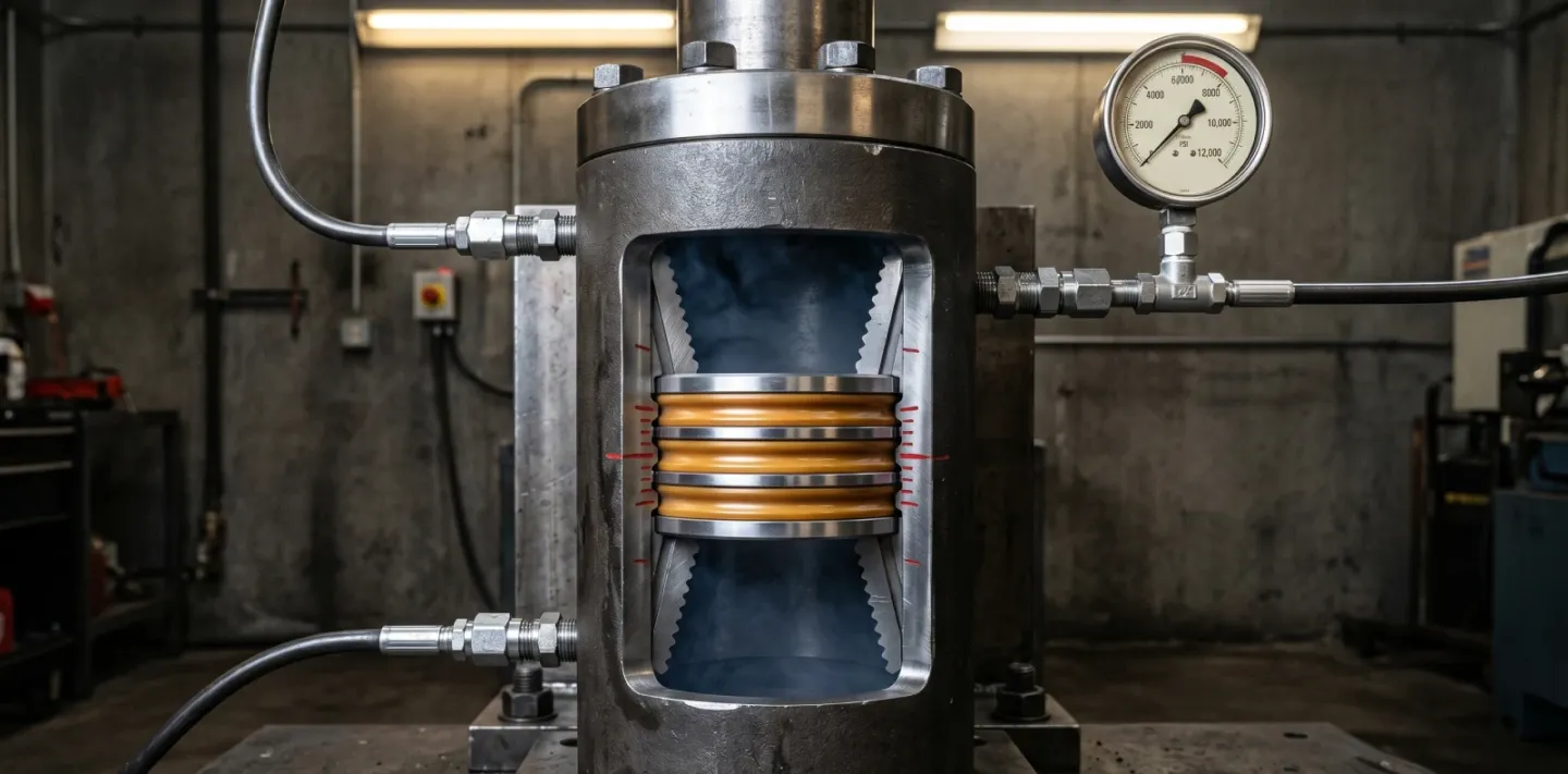
| Pressure Rating (typical) | Up to 10,000 PSI differential (V0/V3 industry standard) | 5,500–10,000+ PSI differential (manufacturer and grade dependent) |
| Temperature Rating (typical) | Up to 400°F (204°C) standard grade | Up to 400°F (204°C) standard; HPHT to 470°F+ |
| Standards | API 11D1 / ISO 14310 — V3 typical, V0 available | API 11D1 / ISO 14310 — V0, V0-R, or V3 |
| Primary Applications | Squeeze cementing, perforation repair, water/gas shut-off, remedial cementing | Well abandonment, zonal isolation, selective stimulation, pressure tests |
| Cost Range (relative) | Comparable to permanent bridge plug; consumed per operation | Cast iron < composite; permanent < retrievable |
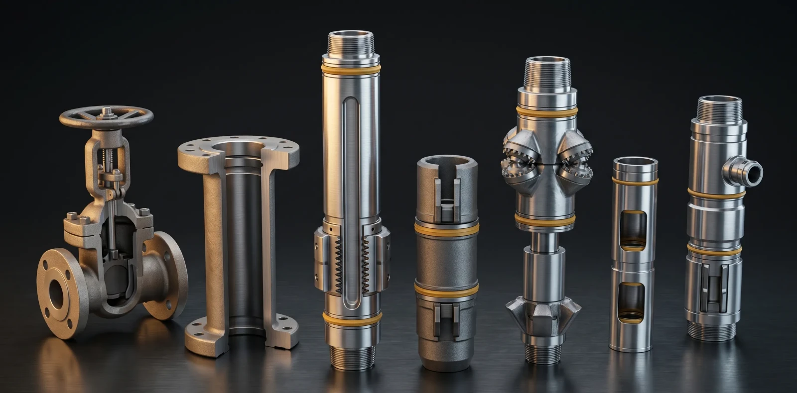
| Manufacturer Examples | Maximus OIGA, Halliburton, SLB BluePlug Max CMR (V3) | Maximus OIGA, Weatherford PBP/ISO-Flex, Baker Hughes MidEXP (V0-R), Expro WRBP |
Maximus OIGA manufactures both cement retainers and bridge plugs to API 11D1 / ISO 14310 — see cast iron and composite bridge plugs or the complete bridge plug specifications. Validation grades are explained in API 11D1 / ISO 14310 validation grades.
Cement Retainer: How It Works, Specs, and Applications
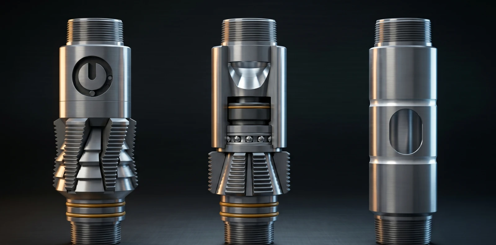
The retainer operates in a defined sequence. A stinger is inserted to open the internal valve, cement is injected into the squeeze interval below the retainer, and the stinger is then withdrawn. The valve closes when the stinger clears, isolating the squeeze zone from above. Residual cement can be left on top of the retainer to serve as a temporary plug.
Three setting methods are standard. Wireline-set retainers use an electrically fired slow-burning charge in the setting tool; the assembly shears free once packoff is achieved. Drillpipe and threaded-tubing systems set the retainer through tubing rotation. Coiled tubing uses a dedicated tubing setting tool. Wireline setting is preferred when depth control is the priority.
Cement Retainer — Key Specifications
| Specification | Value |
|---|---|
| Pressure Rating (typical) | Up to 10,000 PSI differential |
| Temperature Rating (typical) | Up to 400°F (204°C) |
| Setting Methods | Wireline, drillpipe/tubing, coiled tubing |
| Construction Material | Cast iron (compact for drillout) |
| Design Verification Standard | API 11D1 / ISO 14310 — V3 typical, V0 available |
Cement retainers are used where retrievable packers carry placement risk. They prevent backflow when cement dehydration is not expected, isolate the squeeze interval from reverse-out pressure, and remove the risk of cementing a retrievable packer in the hole. Standard applications include squeeze cementing, casing leak repair, perforation isolation, water and gas shut-off, and multi-zone selective squeezing.
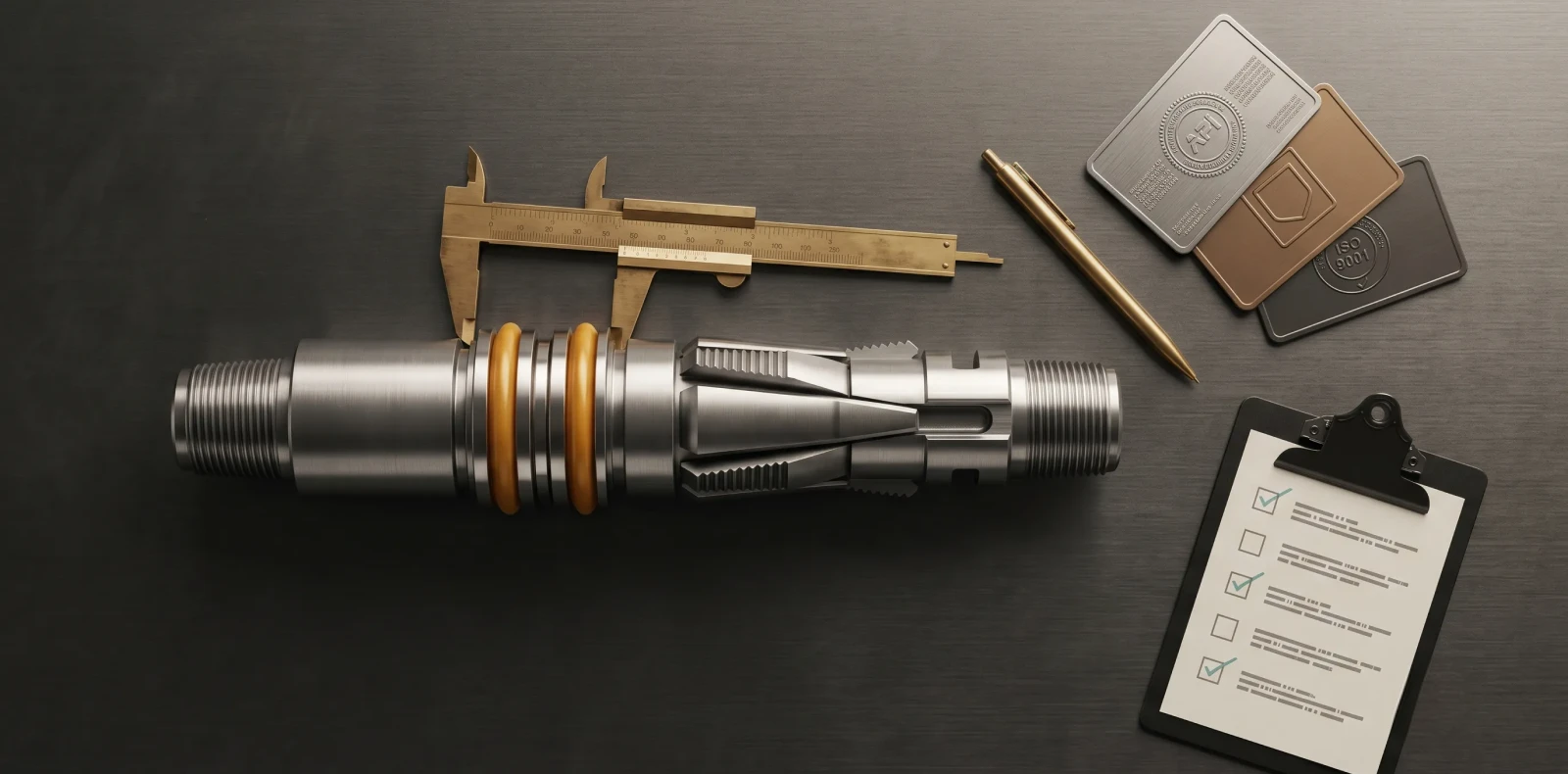
Design verification follows API 11D1 / ISO 14310 — typically Grade V3 (gas test, 20 cm³ leak rate over the hold period), with V0 (bubble-tight gas seal) available for higher-rated service. Maximus OIGA produces cement retainers in wireline-set and tubing-set configurations under API Q1 quality systems with ISO 14310 design verification.
Bridge Plug: How It Works, Specs, and Applications
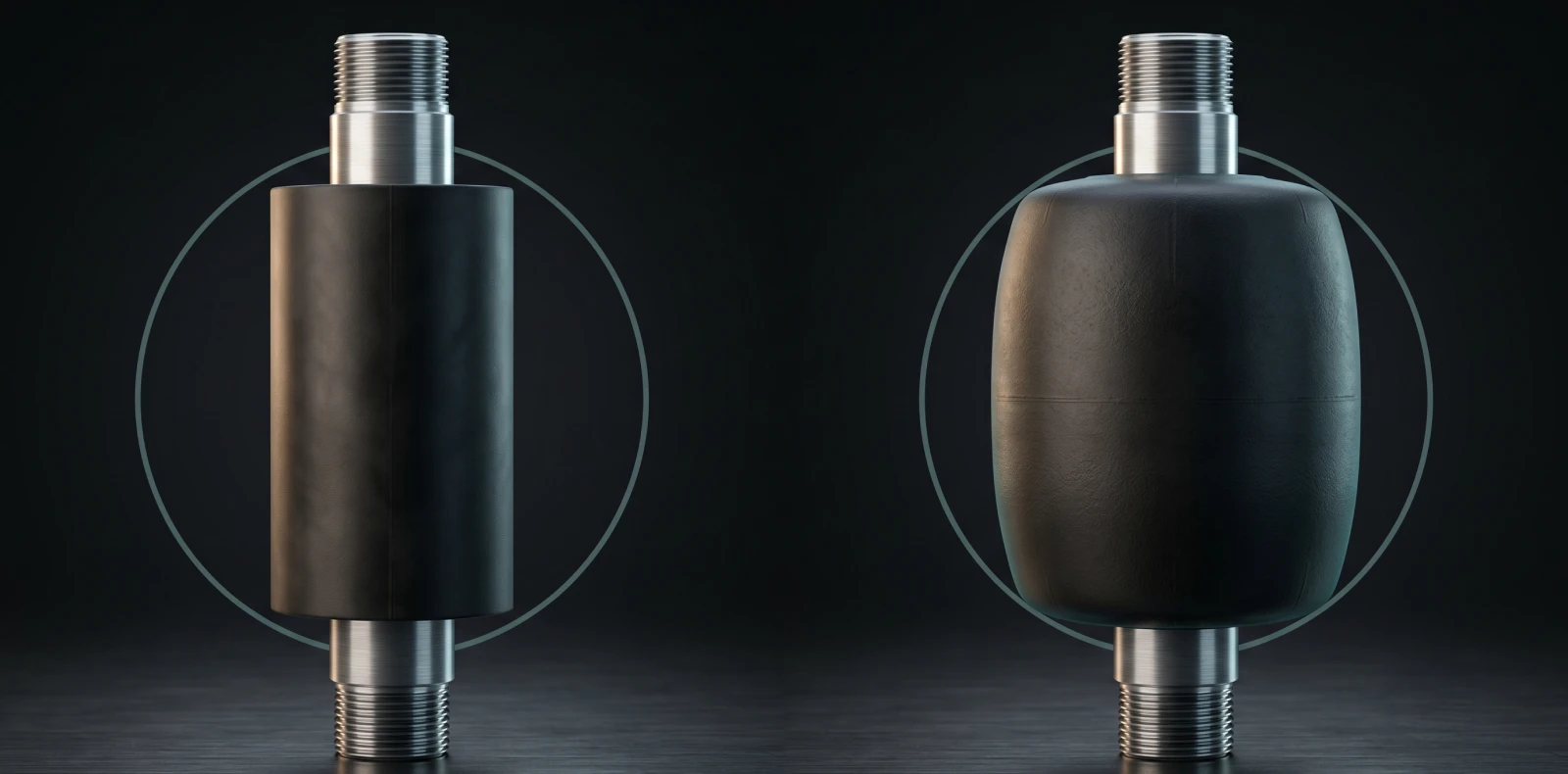
Bridge plugs are supplied in two configurations. Permanent plugs remain in the well and are drilled out at end of service; retrievable plugs are mechanically released and pulled with a standard GS pulling tool. Cast iron permanent plugs deliver the highest pressure ratings and proven long-term reliability for abandonment. Composite plugs use engineered polymer-composite slips and elements that drill out faster than cast iron, reducing milling time and rig hours. Maximus OIGA manufactures both materials as a bridge plug manufacturer, with 200+ installations across India, the Middle East, and Southeast Asia.
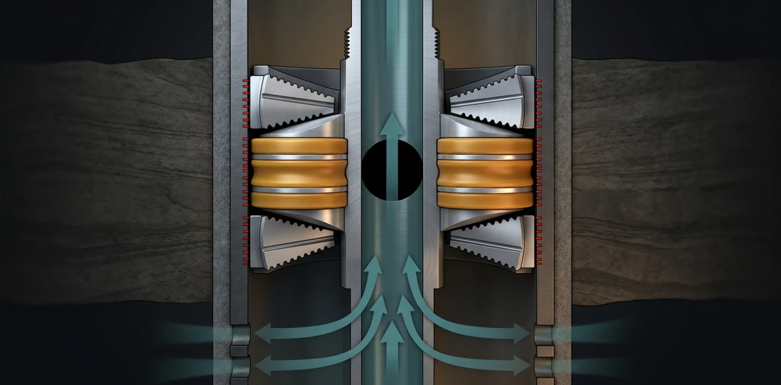
Setting methods include wireline (slickline and e-line) with #10 pressure setting assemblies, coiled tubing with #10 hydraulic setting tools, and drillpipe. Bi-directional slips and an equalizing valve allow pressure to balance before mechanical release — critical when pressure reversals are expected.
Bridge Plug — Key Specifications (Cast Iron vs Composite)
| Specification | Cast Iron Permanent | Composite Retrievable |
|---|---|---|
| Pressure Rating (industry range) | Up to 10,000 PSI differential | 5,500–10,000 PSI differential |
| Temperature Rating | Up to 400°F (204°C); HPHT to 470°F | Up to 400°F (204°C) |
| Standard Grades (API 11D1) | V0, V3 typical | V0-R, V3 |
| Drillout Profile | Milling operation required | Faster drillout, reduced milling |
| Best-Fit Use | Permanent P&A, zonal abandonment | Temporary isolation, selective stimulation |
Validation follows API 11D1 / ISO 14310, which defines six standard grades (V6 lowest, V1 highest) plus the special V0 bubble-tight gas seal grade; V0-R designates the retrievable V0 variant. Industry envelopes range from 5,500 PSI / 250°F at V0-R up to 470°F / 20,000 PSI for HPHT permanent designs per published SPE papers.
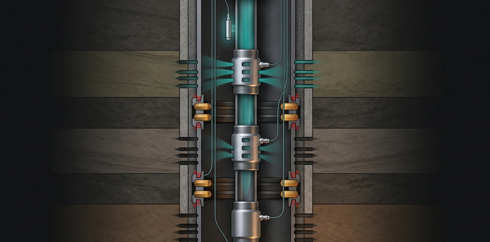
Standard applications include permanent well abandonment, temporary abandonment, zonal isolation during stimulation and fracturing, pressure testing, and selective treatment isolation. In P&A, the bridge plug functions as the mechanical primary barrier and an abandonment cement plug above it acts as the secondary barrier, satisfying the two-independent-barrier rule under API RP 65-3, NORSOK D-010, and ISO 16530-1.
Need expert guidance on the right solution?
Talk to our engineers about your project requirements.
Which Is Right for Your Well? A Decision Framework
The selection rule is operation-driven, not preference-driven. The decision framework below maps five common well-isolation operations to the correct tool, with the technical reason in each case. Use this to justify the choice in a procurement memo or operations plan.
Decision Framework — Match the Operation to the Tool
| If your operation is... | Choose... | Because... |
|---|---|---|
| Remedial squeeze cementing — casing leak or perforation repair | Cement Retainer | Valve and stinger interface enable precise cement placement and backflow prevention without cementing a retrievable packer in the hole. |
| Permanent well abandonment / P&A | Bridge Plug (cast iron permanent) PLUS abandonment cement plug | Two-barrier regulatory requirement — bridge plug is the mechanical primary barrier; cement on top is the verified secondary barrier. |
| Selective stimulation — frac one zone while protecting another | Retrievable Bridge Plug | Pressure barrier must be removed after the stimulation campaign; no cement placement is needed. |
| Water or gas shut-off in a producing well | Cement Retainer first, then evaluate Bridge Plug | Cement retainer handles the squeeze step; bridge plug is added only if the zone needs permanent isolation afterward. |
| Temporary workover suspension or wellhead repair | Retrievable Bridge Plug | Provides a temporary pressure barrier for surface work and is recovered when the well is returned to service. |
A tie-breaker for marginal cases: if the operation involves pumping something into the formation under pressure, choose a cement retainer. If the operation involves sealing off something for protection, choose a bridge plug. Multi-barrier P&A designs combine the two — bridge plug as the mechanical primary barrier, abandonment cement plug placed through a cement retainer as the verified secondary barrier, consistent with API RP 65-3 / NORSOK D-010 P&A standards.
Frequently Asked Questions
Q1. What is the difference between a packer and a bridge plug?
A packer isolates the annular space between tubing and casing while allowing controlled production or injection through the tubing string, and it stays in the well during production. A bridge plug isolates the wellbore itself — a sealed barrier in the casing with no flow path through it — used for abandonment, isolation, or temporary suspension. The visual tell: a packer has a tubing string running through it; a bridge plug does not. Both are governed by API 11D1 / ISO 14310. Maximus OIGA manufactures both.
Q2. Can a cement retainer and a bridge plug be used in the same well operation?
Yes — the two are commonly used together in plug and abandonment operations. The typical sequence is to set a permanent bridge plug as the mechanical primary barrier above the reservoir, then set a cement retainer higher in the well to inject the abandonment cement plug. The cement then acts as the verified secondary barrier. Many jurisdictions require two independent barriers between the reservoir and surface, which is why the two tools are complementary rather than substitutes. Reference standards: API RP 65-3, NORSOK D-010, OGUK/OEUK Decommissioning Guidelines.
Q3. How is a cement retainer set in the wellbore?
Three setting methods are standard. Wireline-set uses an electrically fired slow-burning charge in the setting tool; the assembly shears free once packoff is achieved. Drillpipe or threaded-tubing setting uses tubing rotation. Coiled tubing uses a dedicated tubing setting tool. After the retainer is set, a stinger is run on tubing, drillpipe, or coiled tubing and inserted into the retainer to open the valve and pump cement. Withdrawing the stinger closes the valve and isolates the squeeze zone. Wireline setting is preferred when depth control is the priority.
Q4. What is the difference between a bridge plug and a frac plug?
A frac plug uses an open-mandrel design with a ball — dropped or pre-installed — providing isolation only during a single frac stage in plug-and-perf hydraulic fracturing. It is drilled or dissolved out as a batch after the campaign. A bridge plug uses a sealed-mandrel design with no flow path, providing permanent or retrievable isolation independent of any ball. Bridge plugs are designed for longer-term isolation such as abandonment, workover suspension, or zonal protection during treatment. The mandrel ID is the visual tell — frac plugs have an open ID, bridge plugs sealed.
Q5. What API and ISO standards apply to cement retainers and bridge plugs?
The primary standard is API Specification 11D1 / ISO 14310 — Petroleum and natural gas industries, downhole equipment, packers and bridge plugs. Design validation runs six standard grades (V6 lowest through V1 highest) plus the special V0 bubble-tight gas seal with no permitted leak rate during the hold period; V0-R is the retrievable V0 variant. Quality control is a separate axis: Q3, Q2, and Q1 (highest manufacturing verification). Maximus OIGA holds API Q1 and ISO 14310 for its packer and bridge plug product families. P&A operations also reference API RP 65-3, NORSOK D-010, and ISO 16530-1
Discuss Your Well Conditions with Maximus OIGA Engineers
For squeeze cementing, request cement retainer specifications. For zonal isolation or plug and abandonment, request bridge plug specifications — cast iron and composite, qualified to API 11D1 / ISO 14310. Maximus OIGA's engineering team reviews well conditions, completion design, and operating envelope before recommending the correct tool grade and configuration. We support 200+ installations across India, the Middle East, and Southeast Asia.
Related Blogs
More Information
Related News & Insights
ISO 14310 & API 11D1 Validation Grades: V6 to V0 Explained
Many engineers assume a higher V-number means a tougher packer. It is the opposite. Under ISO 14310 packer validation grades, the scale runs from V6, the minimum, down to V0, the most demanding gas-tight grade — so a lower number means more severe testing, not less. For anyone just trying to understand the basics, that inversion is where most confusion starts.
June 8, 2026
Intelligent Well Completion: Technologies, Market Trends & Equipment Guide
Imagine adjusting flow from each zone of a multi-zone reservoir in real time, from surface, without ever sending a rig downhole. That is the promise of intelligent well completion, and for an engineer just trying to understand the basics, the concept is more concrete than the marketing suggests once you see how the pieces connect.
June 8, 2026
Oil & Gas Equipment Companies in India: Manufacturer Directory 2026
Navigating India's oilfield equipment landscape is challenging without a comprehensive directory, and procurement teams asking "who are the best manufacturers for this?" often lose weeks to vendor research. This directory profiles the key oil and gas equipment companies in India with verified capabilities, so you can build a qualified shortlist faster.
June 8, 2026
Liner Hanger Types & Selection: Complete Engineering Reference
What type of liner hanger does your well design require? The answer depends on setting depth, liner weight, and whether hydraulic or mechanical actuation suits the hole. For an engineer just trying to understand the basics, the liner hanger types break down into three categories — and knowing how they differ is the first step toward specifying the right one.
June 6, 2026
Packer in Well Completion- Functions, Types & How to Select the Right One
Packers are installed in nearly every cased-hole completion worldwide, yet the packer in well completion remains one of the most consequential pieces of downhole hardware to understand. For anyone just trying to understand the basics, the packer is the component that makes controlled production possible by sealing the space between the tubing and the casing.
June 6, 2026
Swellable Packer Applications- Open Hole, HPHT & Water Shutoff Guide
When an operator needs to isolate an open hole section in a horizontal well without cementing, swellable packer applications offer the most direct route to a reliable annular seal. Across open hole zonal isolation, multistage fracturing, and water shutoff, the swellable packer has become the interventionless tool completion engineers reach for when running cement or mechanical packers is impractical or costly
June 6, 2026
How to Choose an Oilfield Equipment Supplier A Procurement Guide
Choosing the wrong oilfield equipment supplier does not just waste procurement budget; it risks downhole failures that cost ten times the equipment price. Knowing how to choose an oilfield equipment supplier means looking past the catalog and the quotation to the evidence that a vendor can actually deliver safety-critical completion equipment. Procurement engineers who get this right treat the decision as risk management, not purchasing
June 6, 2026
Top Downhole Tool Manufacturers & Suppliers 2026 Global Guide
The global downhole tools market exceeds 5 billion US dollars annually, and the list of companies claiming to serve it is far longer than any procurement team has time to vet. This guide narrows the field: it covers how to evaluate a downhole tool manufacturer, then profiles the global majors, the India-based OEMs, and Maximus OIGA — fairly, with real pros and cons, so you can build an RFQ shortlist without months of vendor research.
June 6, 2026
Sliding Sleeve Applications in Well Completion Types & Selection Guide
Sliding sleeves have evolved from simple open/close mechanisms into precision multi-zone flow control devices, and understanding their applications is now central to modern well completion design. This guide covers what a sliding sleeve does, the main types, real downhole applications, and how to select the right one — written for engineers trying to understand the basics and go a level deeper, not for a sales pitch.
June 6, 2026
Bridge Plug Setting Procedure Step-by-Step Guide for Wireline Operations
How do you properly set a bridge plug using wireline? This step-by-step procedure covers tool string assembly, depth correlation, setting tool activation, and pressure testing for confirmed well isolation. It is written for field engineers who need the exact sequence right the first time, with 200+ Maximus OIGA installations across India, the Middle East, and Southeast Asia behind it
June 6, 2026